
ASM2464PD-test

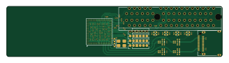
About the ASM2464PD-test PCB
ASM2464PD-test is an open source PCB design by a-little-wifi, published on GitHub. It is a 4-layer board measuring 81.8 × 19 mm, with 93 components from 26 distinct parts.
Other key parts include the SPI_SOIC-8 and SPI_DFN-8. By type, the board carries 42 resistors, 21 capacitors, 16 diodes, 10 connectors, 3 ICs and 1 crystal.
From the project
Messing around with ASM2464PD symbol and footprint
The ASM2464PD is meant for USB4 (or Thunderbolt 3 and USB3.x too, afaik) to NVMe SSD enclosures, and the ASM2464PDX is meant for USB4/TB to general PCIe devices such as GPUs. I've read that the PD one also works for general PCIe devices but it's not officially supported. An AX210 wifi card worked on an ASM2464PD (non-X) enclosure for me, haven't tried GPUs yet.
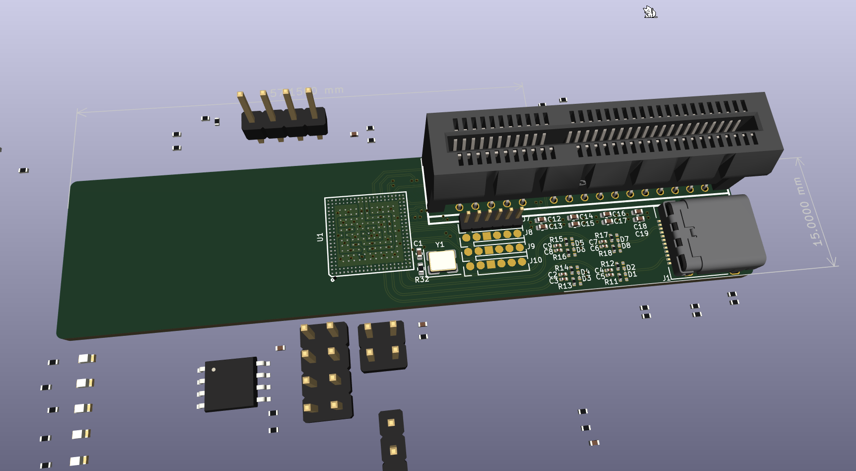
Main components on the ASM2464PD-test
ASM2464PD-test bill of materials (BOM)
93 components, 26 distinct parts.
| Qty | Part | Footprint | Refs |
|---|---|---|---|
| 1 | ~ | ASM2464PD | U1 |
| 1 | SPI_SOIC-8 | SOIC-8_5.3x5.3mm_P1.27mm | U2 |
| 1 | SPI_DFN-8 | DFN-8-1EP_3x2mm_P0.5mm_EP1.3x1.5mm | U3 |
| 1 | 25MHz | Crystal_SMD_3225-4Pin_3.2x2.5mm | Y1 |
| 1 | USB_C_Receptacle | USB_C_Receptacle_Amphenol_12401610E4-2A | J1 |
| 1 | SPIheader | PinHeader_2x04_P2.54mm_Vertical | J2 |
| 1 | Bus_PCI_Express_x4 | PCIe_x4_tht_open | J3 |
| 1 | chip-annoyers | PinHeader_2x02_P2.54mm_Vertical | J4 |
| 1 | UART | PinHeader_1x04_P2.54mm_Vertical | J5 |
| 1 | I2C | PinHeader_1x04_P2.54mm_Vertical | J6 |
| 4 | Conn_01x06 | PinHeader_1x06_P1.27mm_Vertical | J7, J8, J9, J10 |
| 8 | ~ | D_0201_0603Metric | D1, D2, D3, D4, D5, D6, D7, D8 |
| 8 | ~ | LED_0603_1608Metric | D9, D10, D11, D12, D13, D14, D15, D16 |
| 1 | 10p | C_0402_1005Metric | C1 |
| 8 | 0.33u | C_0201_0603Metric | C2, C3, C4, C5, C6, C7, C8, C9 |
| 2 | 1u | C_0402_1005Metric | C10, C21 |
| 1 | 220p | C_0402_1005Metric | C11 |
| 8 | 0.22u | C_0402_1005Metric | C12, C13, C14, C15, C16, C17, C18, C19 |
| 1 | 0.1u | C_0402_1005Metric | C20 |
| 10 | 1k | R_0402_1005Metric | R1, R2, R20, R24, R26, R29, R39, R41 +2 |
Show 6 more
| Qty | Part | Footprint | Refs |
|---|---|---|---|
| 10 | 0Ω | R_0402_1005Metric | R3, R4, R5, R6, R7, R8, R25, R30 +2 |
| 8 | 4.7k | R_0402_1005Metric | R9, R27, R28, R34, R35, R36, R37, R38 |
| 4 | 10k | R_0402_1005Metric | R10, R21, R22, R23 |
| 8 | 220k | R_0201_0603Metric | R11, R12, R13, R14, R15, R16, R17, R18 |
| 1 | 12.1k | R_0402_1005Metric | R32 |
| 1 | 100k | R_0402_1005Metric | R33 |
ASM2464PD-test design files
The KiCad project lives in the a-little-wifi/ASM2464PD-test repository on GitHub; these links point at the commit this page was built from.
- LayoutASM2464PD-test.kicad_pcb
- SchematicASM2464PD-test.kicad_sch
ASM2464PD-test: common questions
How big is the ASM2464PD-test PCB?
The ASM2464PD-test measures 81.8 × 19 mm, has 4 copper layers and is 1.6 mm thick.
How many components are on the ASM2464PD-test?
93 components, from 26 distinct parts. The full bill of materials is listed on this page.
Where can I download the ASM2464PD-test design files?
From the a-little-wifi/ASM2464PD-test repository on GitHub, which has the KiCad layout and the schematic; the links under Design files point to each one.
Can I use the ASM2464PD-test design in my own project?
The repository has no license, so all rights stay with a-little-wifi. Use it as a reference, and ask the author before reusing the design.