De0raspi

About the De0raspi PCB
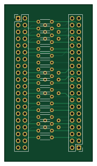
De0raspi is an open source PCB design by Gamby-1791, published on GitHub under the GPL-3.0 license. It is a 2-layer board measuring 33 × 58.4 mm, with 28 components from 3 distinct parts.
By type, the board carries 26 resistors and 2 connectors.
From the project
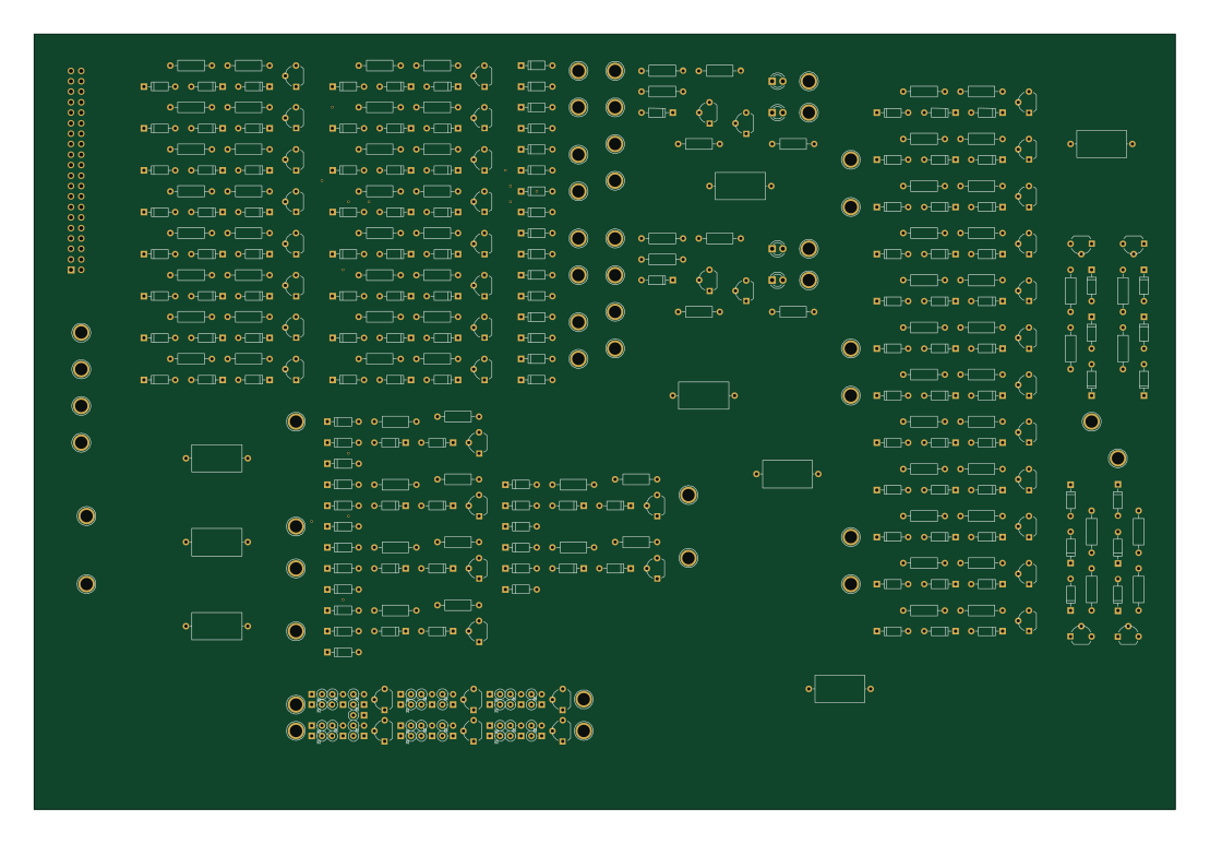
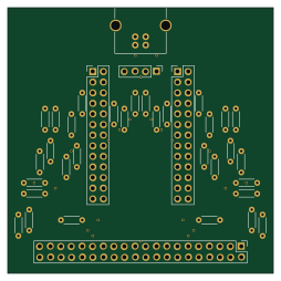
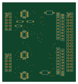
HODE is a 16-bit transistor computer that uses a RaspberryPi for memory and IO. This project includes a simulator and requires a Linux computer (x86 or Raspberry Pi) for software building. The design and PCB layouts are created using KiCad.
De0raspi bill of materials (BOM)
28 components, 3 distinct parts.
| Qty | Part | Footprint | Refs |
|---|---|---|---|
| 1 | DEO_GPIO1 | Pin_Header_Straight_2x20_Pitch2.54mm | J1 |
| 1 | RASPI_GPIO | Pin_Header_Straight_2x20_Pitch2.54mm | J2 |
| 26 | 33 | R_Axial_DIN0204_L3.6mm_D1.6mm_P5.08mm_Horizontal | R1, R2, R3, R4, R5, R6, R7, R8 +18 |
De0raspi design files
The KiCad project lives in the Gamby-1791/H.O.D.E. repository on GitHub; these links point at the commit this page was built from.
De0raspi: common questions
How big is the De0raspi PCB?
The De0raspi measures 33 × 58.4 mm, has 2 copper layers and is 1.6 mm thick.
How many components are on the De0raspi?
28 components, from 3 distinct parts. The full bill of materials is listed on this page.
Where can I download the De0raspi design files?
From the Gamby-1791/H.O.D.E. repository on GitHub, which has the KiCad layout; the links under Design files point to each one.
Can I use the De0raspi design in my own project?
Yes, under the terms of its GPL-3.0 license, which Gamby-1791 chose for the repository.