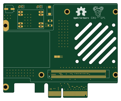
V1

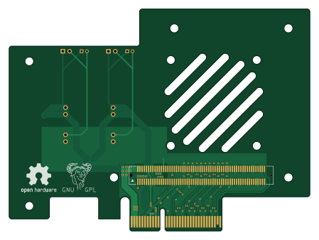
About the V1 PCB
V1 is an open source PCB design by KCORES, published on GitHub under the GPL-3.0 license. It is a 2-layer board measuring 112.1 × 82.8 mm, with 11 components from 8 distinct parts.
Other key parts include the DM02. By type, the board carries 5 connectors, 4 capacitors, 1 IC and 1 test point.
From the project
OCP Mezzanine card V2.0 to standard PCIe slot adapter design
具有SMBUS连接,在部分服务器主板上可能不稳定 With SMBUS connection, may be unstable on some server motherboards
Main components on the V1
V1 bill of materials (BOM)
11 components, 8 distinct parts.
| Qty | Part | Footprint | Refs |
|---|---|---|---|
| 1 | DM02 | DM02 | U1 |
| 1 | Conn_02x40_Top_Bottom | FCI_61082_12xxxxLF | J2 |
| 2 | Conn_01x02 | PinHeader_1x02_P2.54mm_Vertical | J3, J5 |
| 2 | Conn_01x02 | PinHeader_1x02_P2.00mm_Vertical | J4, J6 |
| 1 | TestPoint_2Pole | TestPlot | TP1 |
| 1 | C | CP_Elec_6.3x5.4 | C1 |
| 1 | C | CP_EIA-7343-31_Kemet-D | C2 |
| 2 | C | C_1206_3216Metric | C3, C4 |
V1 design files
The KiCad project lives in the KCORES/OCP2PCIe repository on GitHub; these links point at the commit this page was built from.
V1: common questions
How big is the V1 PCB?
The V1 measures 112.1 × 82.8 mm, has 2 copper layers and is 1.6 mm thick.
How many components are on the V1?
11 components, from 8 distinct parts. The full bill of materials is listed on this page.
Where can I download the V1 design files?
From the KCORES/OCP2PCIe repository on GitHub, which has the KiCad layout; the links under Design files point to each one.
Can I use the V1 design in my own project?
Yes, under the terms of its GPL-3.0 license, which KCORES chose for the repository.