
DummyLoad

About the DummyLoad PCB
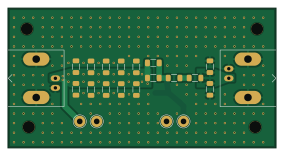
DummyLoad is an open source PCB design by mbasanta, published on GitHub under the MIT license. It is a 2-layer board measuring 71 × 37 mm, with 35 components from 12 distinct parts.
By type, the board carries 26 resistors, 4 test points, 2 connectors, 2 capacitors and 1 diode.
From the project
KiCad project for a 50 ohm RF dummy load board with integrated attenuation and rectified measurement output.
KiCad project for a 50 ohm RF dummy load board with integrated attenuation and rectified measurement output.
This repository contains the schematic, PCB, custom footprint library, and generated manufacturing artifacts for the DummyLoad board.
From the schematic title block and notes: - Design target: 50 ohm dummy load - Rated power (design intent): 10 W - Includes attenuation network: - Note in schematic: "40db Attenuation (use 3x 261 Ohm resistors for 30db)" - Includes a rectified voltage measurement point for RF power estimation (see Dummy Load Voltages for the relationship between…
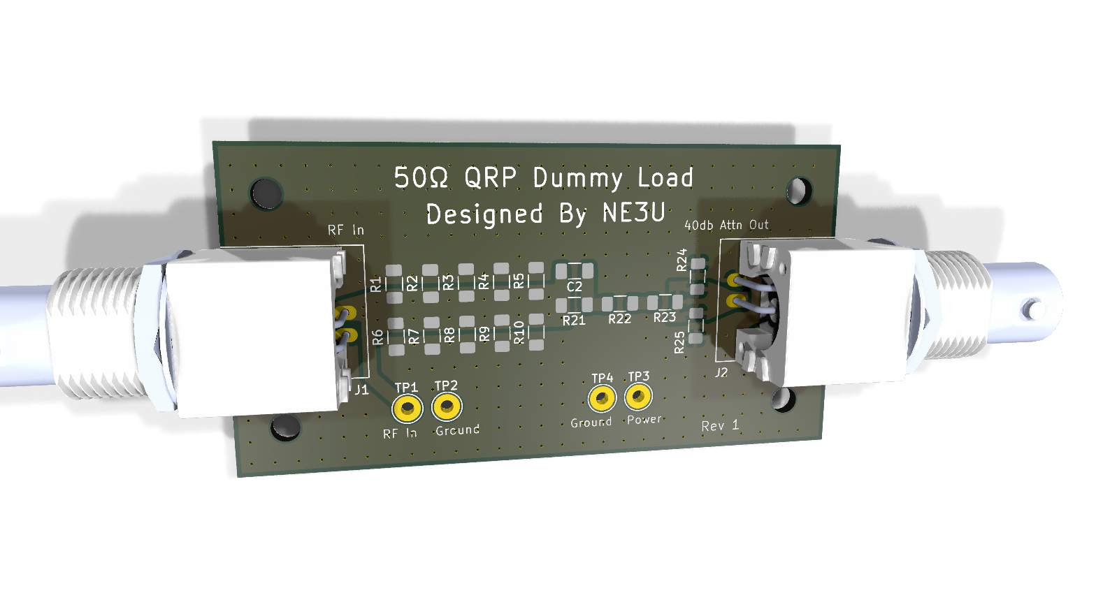
DummyLoad bill of materials (BOM)
35 components, 12 distinct parts — part numbers from the project's BOM.
| Qty | Part | Footprint | Refs |
|---|---|---|---|
| 1 | RF In | BNC_Amphenol_B6252HB-NPP3G-50_Horizontal | J1 |
| 1 | RF Out | BNC_Amphenol_B6252HB-NPP3G-50_Horizontal | J2 |
| 1 | RF In | TestPoint_THTPad_D3.0mm_Drill1.5mm | TP1 |
| 2 | GND | TestPoint_THTPad_D3.0mm_Drill1.5mm | TP2, TP4 |
| 1 | Power Out | TestPoint_THTPad_D3.0mm_Drill1.5mm | TP3 |
| 1 | 1N5711 | Nexperia_CFP3_SOD-123W | D1 |
| 1 | 10nF | C_1206_3216Metric_Pad1.33x1.80mm_HandSolder | C1 |
| 1 | C | C_1206_3216Metric_Pad1.33x1.80mm_HandSolder | C2 |
| 20 | 1K | R_1206_3216Metric_Pad1.30x1.75mm_HandSolder | R1, R2, R3, R4, R5, R6, R7, R8 +12 |
| 3 | 820 | R_1206_3216Metric_Pad1.30x1.75mm_HandSolder | R21, R22, R23 |
| 2 | 102 | R_1206_3216Metric_Pad1.30x1.75mm_HandSolder | R24, R25 |
| 1 | 100K | R_1206_3216Metric_Pad1.30x1.75mm_HandSolder | R26 |
DummyLoad design files
The KiCad project lives in the mbasanta/DummyLoad repository on GitHub; these links point at the commit this page was built from.
- LayoutDummyLoad.kicad_pcb
- SchematicDummyLoad.kicad_sch
- BOMoutput/bom.csv
DummyLoad: common questions
How big is the DummyLoad PCB?
The DummyLoad measures 71 × 37 mm, has 2 copper layers and is 1.6 mm thick.
How many components are on the DummyLoad?
35 components, from 12 distinct parts, with part numbers taken from the project's own BOM. The full bill of materials is listed on this page.
Where can I download the DummyLoad design files?
From the mbasanta/DummyLoad repository on GitHub, which has the KiCad layout, the schematic and the BOM; the links under Design files point to each one.
Can I use the DummyLoad design in my own project?
Yes, under the terms of its MIT license, which mbasanta chose for the repository.