
ATX Boot Delay

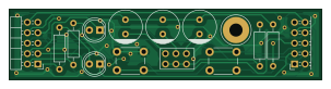
About the ATX Boot Delay PCB
ATX Boot Delay is an open source PCB design by mwrnd, published on GitHub under the BSD-2-Clause license. It is a 2-layer board measuring 75.6 × 17.1 mm, with 14 components from 14 distinct parts.
By type, the board carries 4 resistors, 3 connectors, 3 capacitors, 2 switches and 2 diodes.
From the project
Power-On Boot Delay for ATX Motherboards with 9-Pin Front Panel Header
Delaying a motherboard's BIOS/UEFI boot is a simple trick that solves issues related to the PCIe Specification's 100ms time limit. This can be done by toggling a computer's POWER button, then pressing and holding the RESET button for a second before releasing it. Or, connect a capacitor across the reset pins of an ATX motherboard's Front Panel Header.
This board is a simple 9-Pin Front Panel Header in-line replacement for ATX motherboards that allows choosing capacitor(s) to connect accross the RESET pins to delay boot.
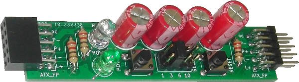
ATX Boot Delay bill of materials (BOM)
14 components, 14 distinct parts.
| Qty | Part | Footprint | Refs |
|---|---|---|---|
| 1 | ATX_FP | PinHeader_2x05_P2.54mm_Horizontal | J1 |
| 1 | ATX_FP | PinSocket_2x05_P2.54mm_Horizontal | J2 |
| 1 | SELECT | PinHeader_2x03_P2.54mm_Vertical | J3 |
| 1 | POWER | SW_PUSH_6mm | SW1 |
| 1 | RESET | SW_PUSH_6mm | SW2 |
| 1 | POWER | LED_D5.0mm | D1 |
| 1 | HDD | LED_D5.0mm | D2 |
| 1 | 330u | C_Radial_D8.0mm_H11.5mm_P3.50mm | C1 |
| 1 | 680u | C_Radial_D8.0mm_H11.5mm_P3.50mm | C2 |
| 1 | 1000u | C_Radial_D8.0mm_H11.5mm_P3.50mm | C3 |
| 1 | 7.5 | R_Axial_DIN0207_L6.3mm_D2.5mm_P10.16mm_Horizontal | R0 |
| 1 | 110 | R_Axial_DIN0207_L6.3mm_D2.5mm_P10.16mm_Horizontal | R1 |
| 1 | 220 | R_Axial_DIN0207_L6.3mm_D2.5mm_P10.16mm_Horizontal | R2 |
| 1 | 330 | R_Axial_DIN0207_L6.3mm_D2.5mm_P10.16mm_Horizontal | R3 |
ATX Boot Delay design files
The KiCad project lives in the mwrnd/ATX_Boot_Delay repository on GitHub; these links point at the commit this page was built from.
- LayoutATX_Boot_Delay.kicad_pcb
- SchematicATX_Boot_Delay.kicad_sch
ATX Boot Delay: common questions
How big is the ATX Boot Delay PCB?
The ATX Boot Delay measures 75.6 × 17.1 mm, has 2 copper layers and is 1.6 mm thick.
How many components are on the ATX Boot Delay?
14 components, from 14 distinct parts. The full bill of materials is listed on this page.
Where can I download the ATX Boot Delay design files?
From the mwrnd/ATX_Boot_Delay repository on GitHub, which has the KiCad layout and the schematic; the links under Design files point to each one.
Can I use the ATX Boot Delay design in my own project?
Yes, under the terms of its BSD-2-Clause license, which mwrnd chose for the repository.