
AC-to-DC-converter

About the AC-to-DC-converter PCB
AC-to-DC-converter is an open source PCB design by nirav1385, published on GitHub. It is a 2-layer board measuring 24.5 × 19.1 mm, with 10 components from 7 distinct parts.
By type, the board carries 5 diodes, 2 resistors and 1 capacitor.
From the project
i have created my frist pcb using KiCad-10, 1-layer AC to DC Converter PCB Design.
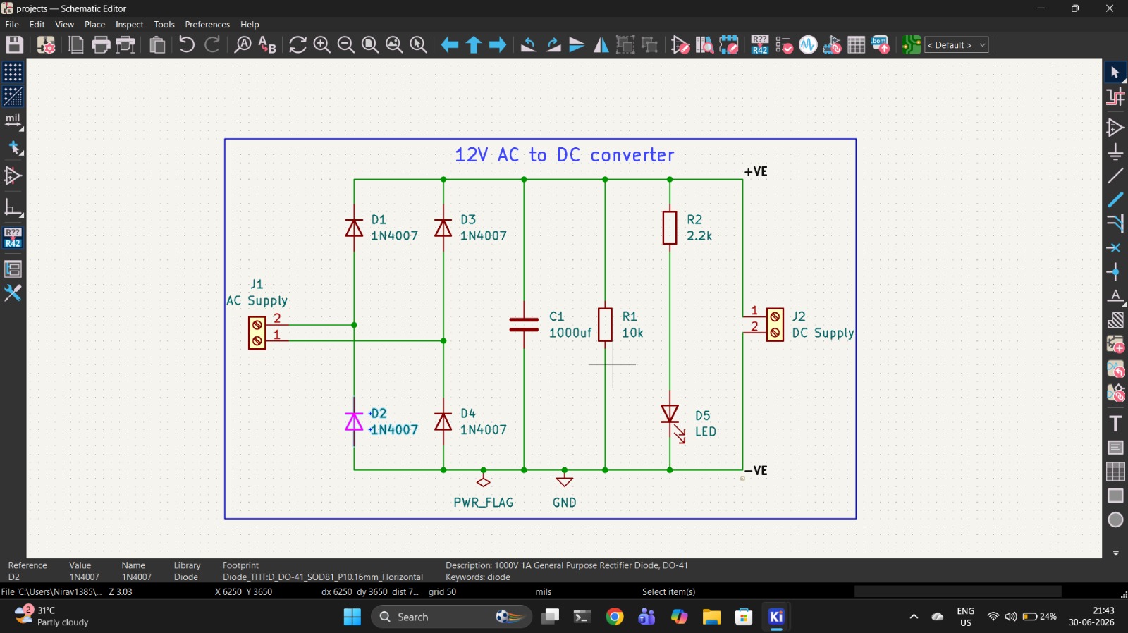
A compact, through-hole 12V AC to DC converter PCB designed in KiCad 10.0. This project converts 12V AC input into smooth DC output using a full-bridge rectifier with filtering, and includes a power indicator LED.
- Project Photos - Features - Circuit Description - Schematic Overview - Bill of Materials (BOM) - PCB Details - How It Works - Getting Started - Manufacturing - Safety Warning - License
AC-to-DC-converter bill of materials (BOM)
10 components, 7 distinct parts.
| Qty | Part | Footprint | Refs |
|---|---|---|---|
| 1 | AC Supply | TerminalBlock_MaiXu_MX126-5.0-02P_1x02_P5.00mm | AC IN (J1) |
| 1 | DC Supply | TerminalBlock_MaiXu_MX126-5.0-02P_1x02_P5.00mm | DC OUT (J2) |
| 4 | 1N4007 | D_DO-41_SOD81_P10.16mm_Horizontal | D1, D2, D3, D4 |
| 1 | LED | LED_D5.0mm | D5 |
| 1 | 1000uf | CP_Radial_D8.0mm_P3.50mm | C1 |
| 1 | 10k | R_Axial_DIN0204_L3.6mm_D1.6mm_P7.62mm_Horizontal | R1 |
| 1 | 2.2k | R_Axial_DIN0204_L3.6mm_D1.6mm_P7.62mm_Horizontal | R2 |
AC-to-DC-converter design files
The KiCad project lives in the nirav1385/AC-to-DC-converter-PCB repository on GitHub; these links point at the commit this page was built from.
- Layoutac_to_dc_converter.kicad_pcb
- Schematicac_to_dc_converter.kicad_sch
AC-to-DC-converter: common questions
How big is the AC-to-DC-converter PCB?
The AC-to-DC-converter measures 24.5 × 19.1 mm, has 2 copper layers and is 1.6 mm thick.
How many components are on the AC-to-DC-converter?
10 components, from 7 distinct parts. The full bill of materials is listed on this page.
Where can I download the AC-to-DC-converter design files?
From the nirav1385/AC-to-DC-converter-PCB repository on GitHub, which has the KiCad layout and the schematic; the links under Design files point to each one.
Can I use the AC-to-DC-converter design in my own project?
The repository has no license, so all rights stay with nirav1385. Use it as a reference, and ask the author before reusing the design.