
AC2DC

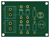
About the AC2DC PCB
AC2DC is an open source PCB design by riteshh27, published on GitHub under the MIT license. It is a 2-layer board measuring 43.2 × 32.6 mm, with 10 components from 5 distinct parts.
By type, the board carries 5 diodes, 2 connectors, 2 resistors and 1 capacitor.
From the project
AC to DC converter PCB (full-wave bridge rectifier) — KiCad project
A simple, compact AC-to-DC converter PCB designed in KiCad. Converts AC mains/transformer output to a smoothed DC output, with an onboard LED power indicator.
The board implements a classic full-wave bridge rectifier followed by capacitive smoothing:
- Rectification: 4× 1N4007 diodes (D1–D4) in a full-wave bridge configuration - Smoothing: Electrolytic capacitor (C1) filters the rectified output - Power indicator: LED (D5) with current-limiting resistor - I/O: Two screw terminals (J1, J2) for AC input and DC output connections - Load/bias resistors: R1, R2
AC2DC bill of materials (BOM)
10 components, 5 distinct parts — part numbers from the project's BOM.
| Qty | Part | Footprint | Refs |
|---|---|---|---|
| 2 | SCREW_TERMINAL_01X02 Screw_Terminal_01x02 | TerminalBlock_CUI_TB007-508-02_1x02_P5.08mm_Horizontal | J1, J2 |
| 4 | 1N4007 | D_DO-41_SOD81_P10.16mm_Horizontal | D1, D2, D3, D4 |
| 1 | LED | LED_D5.0mm | D5 |
| 1 | C | C_Radial_D6.3mm_H11.0mm_P2.50mm | C1 |
| 2 | R | R_Axial_DIN0207_L6.3mm_D2.5mm_P10.16mm_Horizontal | R1, R2 |
AC2DC design files
The KiCad project lives in the riteshh27/AC2DC repository on GitHub; these links point at the commit this page was built from.
- LayoutAC2DC.kicad_pcb
- SchematicAC2DC.kicad_sch
- BOMAC2DC_BOM.csv
AC2DC: common questions
How big is the AC2DC PCB?
The AC2DC measures 43.2 × 32.6 mm, has 2 copper layers and is 1.6 mm thick.
How many components are on the AC2DC?
10 components, from 5 distinct parts, with part numbers taken from the project's own BOM. The full bill of materials is listed on this page.
Where can I download the AC2DC design files?
From the riteshh27/AC2DC repository on GitHub, which has the KiCad layout, the schematic and the BOM; the links under Design files point to each one.
Can I use the AC2DC design in my own project?
Yes, under the terms of its MIT license, which riteshh27 chose for the repository.