
HVI

About the HVI PCB
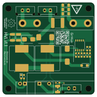
HVI is an open source PCB design by Rootthecause, published on GitHub under the CERN-OHL-W-2.0 license. It is a 2-layer board measuring 48 × 48 mm, with 31 components from 22 distinct parts.
Other key parts include the VIPER06-SSOP-10. By type, the board carries 8 resistors, 7 diodes, 7 capacitors, 3 connectors, 2 inductors and 1 IC.
From the project
The High Voltage Indicator (Light) is a device that indicates the presence of voltages above 60 V.
I've designed a High Voltage Indicator in accordance with EV 5.4.8 (Rules 2026_v1.0) to replace our heavy and bulky voltmeter. This device can supply between 5 V and 24 V (depending on the configuration) at a maximum of 1 W (isolated) or 3 W (non-isolated) from a 40 V to 800 V source. Two LEDs on the back indicate the presence of high voltage, so it can be mounted either directly to a viewing window in the TSAC or elsewhere with a cable to an external LED. As it is basically an HV step-down converter, it can also be used for any other application, e.g. to start a DC/DC (for LVS supply) from…

Main components on the HVI
HVI bill of materials (BOM)
31 components, 22 distinct parts — part numbers from the project's BOM.
| Qty | Part | Footprint | Refs |
|---|---|---|---|
| 1 | VIPER06-SSOP-10 | SSOP-10_3.9x4.9mm_P1.00mm | U1 |
| 3 | CONN_01X02 Conn_01x02 | Molex_Micro-Fit_3.0_43650-0215_1x02_P3.00mm_Vertical | J1, J2, J3 |
| 1 | ≤ 500 mA, solder Fuse Clips F1.1 and F1.2 and insert F1 | Fuseholder0,25Zoll_32mm_littlefuse_102_122 | F1 |
| 1 | SOLDERJUMPER_3_OPEN SolderJumper_3_Open | SolderJumper-3_P1.3mm_Open_RoundedPad1.0x1.5mm_NumberLabels | JP1 |
| 1 | PEME1-S12-S5-S | CONV_PEME1-S5-S5-S | PS1 |
| 1 | VS-E7FX0212-M3/I | D_SMF | D1 |
| 2 | US3M-13 | D_SMC | D2, D6 |
| 3 | LED | LED_0603_1608Metric_Pad1.05x0.95mm_HandSolder | D3, D4, D5 |
| 1 | P6SMB13A | D_SMB | D7 |
| 2 | 4.7 mH | L_Bourns_SRR1208_12.7x12.7mm | L1, L2 |
| 1 | 220N 220n | C_2220_5650Metric | C1 |
| 1 | 100NF 100nF | C_0603_1608Metric_Pad1.08x0.95mm_HandSolder | C2 |
| 1 | 2.2µF | C_0603_1608Metric_Pad1.08x0.95mm_HandSolder | C3 |
| 1 | 22NF 22nF | C_0603_1608Metric_Pad1.08x0.95mm_HandSolder | C7 |
| 2 | 47µF | C_1210_3225Metric_Pad1.33x2.70mm_HandSolder | C8, C9 |
| 1 | 10µF | C_0603_1608Metric_Pad1.08x0.95mm_HandSolder | C10 |
| 3 | 270 | R_1206_3216Metric_Pad1.30x1.75mm_HandSolder | R1, R2, R3 |
| 1 | 1k | R_0603_1608Metric_Pad0.98x0.95mm_HandSolder | R4 |
| 1 | 27K 27k | R_0603_1608Metric_Pad0.98x0.95mm_HandSolder | R5 |
| 1 | 10K 10k | R_0603_1608Metric_Pad0.98x0.95mm_HandSolder | R7 |
Show 2 more
| Qty | Part | Footprint | Refs |
|---|---|---|---|
| 1 | 150 | R_0603_1608Metric_Pad0.98x0.95mm_HandSolder | R8 |
| 1 | 4K7 4k7 | R_0603_1608Metric_Pad0.98x0.95mm_HandSolder | R9 |
HVI design files
The KiCad project lives in the Rootthecause/HVI repository on GitHub; these links point at the commit this page was built from.
- LayoutHVI.kicad_pcb
- SchematicHVI.kicad_sch
- BOMdoc/bom/BOM.xls
HVI: common questions
How big is the HVI PCB?
The HVI measures 48 × 48 mm, has 2 copper layers and is 1.6 mm thick.
How many components are on the HVI?
31 components, from 22 distinct parts, with part numbers taken from the project's own BOM. The full bill of materials is listed on this page.
Where can I download the HVI design files?
From the Rootthecause/HVI repository on GitHub, which has the KiCad layout, the schematic and the BOM; the links under Design files point to each one.
Can I use the HVI design in my own project?
Yes, under the terms of its CERN-OHL-W-2.0 license, which Rootthecause chose for the repository.