
Fc magicon

About the Fc magicon PCB
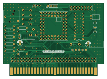
Fc magicon is an open source PCB design by SHIMA-R7, published on GitHub under the MIT license. It is a 2-layer board measuring 90 × 65.8 mm, with 30 components from 28 distinct parts.
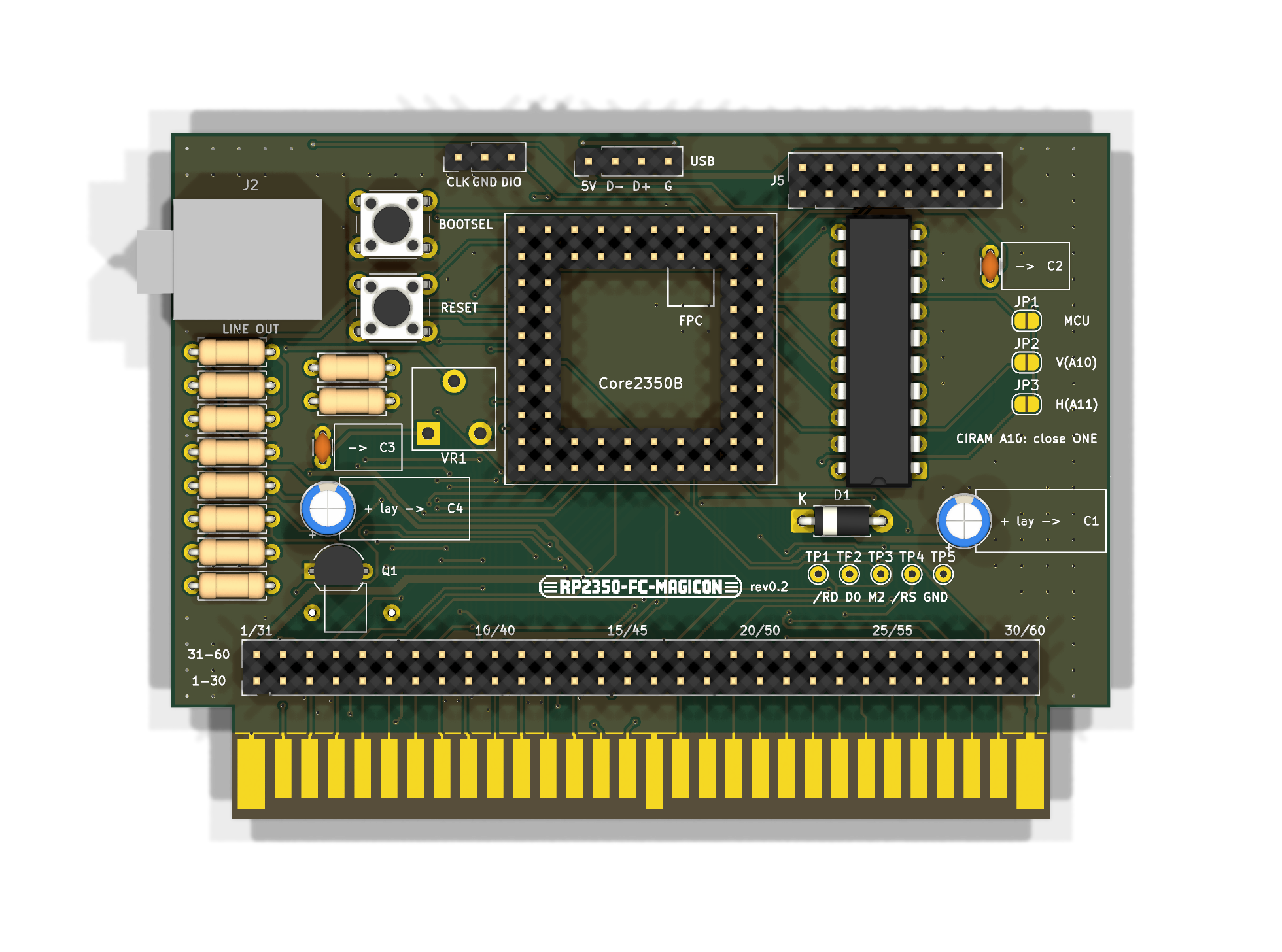
Other key parts include the 74LVC245 (5V->3.3V). By type, the board carries 11 resistors, 9 connectors, 4 capacitors, 2 switches, 1 IC and 1 transistor.
From the project
Famicom cartridge built around one RP2350B (Waveshare Core2350B): PRG/CHR emulation, NSF player, PC-to-Famicom screen streaming. KiCad 10.
Waveshare Core2350B(RP2350B)1枚で作るファミコン用カセット。
- PRG・CHR を RP2350B がリアルタイムにエミュレート(マジコン。NROM/CNROM/UNROM/MMC1/MMC3 などをファームで実装) - NSF 再生(バンク切り替え・WRAM 対応。拡張音源は PWM で46番に混ぜる) - PC→FC 画面転送(PPU の読み出しに直接応答する FC-PICO 方式)
- 基板 rev0.2 の設計が完了(2層、DRC エラー0・未接続0)。未発注・未実装。 - ファームウェア: 動作確認用の bustest(CPU バスでテスト ROM を返して音を鳴らす)と chrtest(PPU に CHR を返して画面に格子模様を出す)、 マジコン本体の magicon(.nes を動かす。NROM/MMC1/UxROM/CNROM/MMC3/AxROM、PRG + CHR 384KB まで)を作成、ビルド済み。未実機。firmware/ - rev0.1 からの変更: USB の予備ランド(J6)、拡張音源の音量用の半固定抵抗 VR1(KOA KVSF637AC104)を追加、 電源・音声の配線を太くした(+5V 0.8mm、VBUS 0.6mm、GND 0.5mm、+3V3 0.4mm、音声 0.4mm)、J5 の 12〜14番を…
Main components on the Fc magicon
Fc magicon bill of materials (BOM)
30 components, 28 distinct parts — part numbers from the project's BOM.
| Qty | Part | Footprint | Refs |
|---|---|---|---|
| 1 | 74LVC245 (5V->3.3V) | DIP-20_W7.62mm | U2 |
| 1 | 2SC1815 | TO-92_Inline_Wide | Q1 |
| 1 | LINE OUT 3.5mm | PJ-324M | J2 |
| 1 | SWD | PinHeader_1x03_P2.54mm_Vertical | J3 |
| 1 | Cart breakout 2x30 | PinHeader_2x30_P2.54mm_Vertical | J4 |
| 1 | Debug 2x8 | PinHeader_2x08_P2.54mm_Vertical | J5 |
| 1 | USB spare land | PinHeader_1x04_P2.54mm_Vertical | J6 |
| 1 | Core2350B P1 | PinHeader_2x08_P2.54mm_Vertical | P1 |
| 1 | Core2350B P2 | PinHeader_2x08_P2.54mm_Vertical | P2 |
| 1 | Core2350B P3 | PinHeader_2x08_P2.54mm_Vertical | P3 |
| 1 | Core2350B P4 | PinHeader_2x08_P2.54mm_Vertical | P4 |
| 1 | BOOTSEL | SW_PUSH_6mm | SW1 |
| 1 | RESET | SW_PUSH_6mm | SW2 |
| 1 | KVSF637AC104 | KOA_SF6_637A | VR1 |
| 1 | 1N4001 | D_DO-41_SOD81_P7.62mm_Horizontal | D1 |
| 1 | 10u | CP_Radial_D5.0mm_P2.00mm | C1 |
| 1 | 100n | C_Disc_D3.0mm_W1.6mm_P2.50mm | C2 |
| 1 | 10n | C_Disc_D3.0mm_W1.6mm_P2.50mm | C3 |
| 1 | 10u (+ to SOUND_OUT) | CP_Radial_D5.0mm_P2.00mm | C4 |
| 2 | 0 | R_Axial_DIN0207_L6.3mm_D2.5mm_P7.62mm_Horizontal | R1, R7 |
Show 8 more
| Qty | Part | Footprint | Refs |
|---|---|---|---|
| 1 | 15k | R_Axial_DIN0207_L6.3mm_D2.5mm_P7.62mm_Horizontal | R2 |
| 1 | 22k | R_Axial_DIN0207_L6.3mm_D2.5mm_P7.62mm_Horizontal | R3 |
| 1 | 4.7k | R_Axial_DIN0207_L6.3mm_D2.5mm_P7.62mm_Horizontal | R4 |
| 1 | 100k | R_Axial_DIN0207_L6.3mm_D2.5mm_P7.62mm_Horizontal | R5 |
| 1 | 10k DNP | R_Axial_DIN0207_L6.3mm_D2.5mm_P7.62mm_Horizontal | R6 |
| 2 | 47k | R_Axial_DIN0207_L6.3mm_D2.5mm_P7.62mm_Horizontal | R8, R10 |
| 1 | 1k | R_Axial_DIN0207_L6.3mm_D2.5mm_P7.62mm_Horizontal | R9 |
| 1 | 100 | R_Axial_DIN0207_L6.3mm_D2.5mm_P7.62mm_Horizontal | R11 |
Fc magicon design files
The KiCad project lives in the SHIMA-R7/fc-magicon repository on GitHub; these links point at the commit this page was built from.
- Layoutkicad/FC-MAGICON.kicad_pcb
- Schematickicad/FC-MAGICON.kicad_sch
- BOMkicad/bom.csv
Fc magicon: common questions
How big is the Fc magicon PCB?
The Fc magicon measures 90 × 65.8 mm, has 2 copper layers and is 1.2 mm thick.
How many components are on the Fc magicon?
30 components, from 28 distinct parts, with part numbers taken from the project's own BOM. The full bill of materials is listed on this page.
Where can I download the Fc magicon design files?
From the SHIMA-R7/fc-magicon repository on GitHub, which has the KiCad layout, the schematic and the BOM; the links under Design files point to each one.
Can I use the Fc magicon design in my own project?
Yes, under the terms of its MIT license, which SHIMA-R7 chose for the repository.