
Rx amp

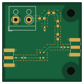
About the Rx amp PCB
Rx amp is an open source PCB design by vlc-utn, published on GitHub. It is a 2-layer board measuring 30 × 30 mm, with 11 components from 8 distinct parts.
Other key parts include the BGA616H6327XTSA1. By type, the board carries 3 connectors, 3 inductors, 3 capacitors, 1 IC and 1 resistor.
Main components on the Rx amp
Rx amp bill of materials (BOM)
11 components, 8 distinct parts.
| Qty | Part | Footprint | Refs |
|---|---|---|---|
| 1 | BGA616H6327XTSA1 Infineon | BGA616H6327XTSA1 | IC1 |
| 1 | Signal_In | SMA_Samtec_SMA-J-P-X-ST-EM1_EdgeMount | J1 |
| 1 | Signal_Out | SMA_Samtec_SMA-J-P-X-ST-EM1_EdgeMount | J2 |
| 1 | Screw_Terminal_01x02 | TerminalBlock_RND_205-00001_1x02_P5.00mm_Horizontal | J3 |
| 2 | LQM18DZ100M70L 10uHy Murata Electronics | L_0603_1608Metric_Pad1.05x0.95mm_HandSolder | L1, L2 |
| 1 | BLM18KG221SN1D Ferrite Beads 220 OHM Murata Electronics | L_0603_1608Metric_Pad1.05x0.95mm_HandSolder | L3 |
| 3 | 530L104KT16 .1uF KYOCERA AVX | C_0402_1005Metric_Pad0.74x0.62mm_HandSolder | C1, C2, C3 |
| 1 | 560112116150 15 Wurth Elektronik | L_0603_1608Metric_Pad1.05x0.95mm_HandSolder | R1 |
Rx amp design files
The KiCad project lives in the vlc-utn/vlc_hardware repository on GitHub; these links point at the commit this page was built from.
- LayoutReceiver/AMP/rx_amp.kicad_pcb
- SchematicReceiver/AMP/rx_amp.kicad_sch
Rx amp: common questions
How big is the Rx amp PCB?
The Rx amp measures 30 × 30 mm, has 2 copper layers and is 1.6 mm thick.
How many components are on the Rx amp?
11 components, from 8 distinct parts. The full bill of materials is listed on this page.
Where can I download the Rx amp design files?
From the vlc-utn/vlc_hardware repository on GitHub, which has the KiCad layout and the schematic; the links under Design files point to each one.
Can I use the Rx amp design in my own project?
The repository has no license, so all rights stay with vlc-utn. Use it as a reference, and ask the author before reusing the design.
More boards in vlc_hardware
LumiCom Transmitter
50 × 42 mm28 parts4LNo license1
LTC6268-10
30 × 40 mm25 parts4LNo license1
LMH34400
34 × 40 mm21 parts4LNo license1
Filtro de preenfasis
25 × 40 mm20 parts2LNo license1
Amplificador TX
30 × 30 mm16 parts2LNo license1
PD
32 × 34 mm9 parts2LNo license1
LED
50 × 35 mm5 parts2LNo license1