
Portable impedance tomography

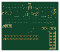
About the Portable impedance tomography PCB
Portable impedance tomography is an open source PCB design by ashtonchase, published on GitHub under the MIT license. It is a 2-layer board measuring 48.3 × 40.9 mm, with 63 components from 25 distinct parts.
Other key parts include the AD5933, ADG1209, LD3985G25R_TSOT23, OPA2836 and AD8130. By type, the board carries 25 connectors, 17 resistors, 13 capacitors and 7 ICs.
It belongs with the iot & wireless designs in this gallery.
From the project
Design of a Portable Impedance Tomography System
Main components on the Portable impedance tomography
Portable impedance tomography bill of materials (BOM)
63 components, 25 distinct parts.
| Qty | Part | Footprint | Refs |
|---|---|---|---|
| 1 | AD5933 | SSOP-16_5.3x6.2mm_Pitch0.65mm | U2 |
| 2 | ADG1209 | TSSOP-16_4.4x5mm_Pitch0.65mm | U3, U9 |
| 1 | LD3985G25R_TSOT23 | TSOT-23-5 | U5 |
| 2 | OPA2836 | TSSOP-10_3x3mm_Pitch0.5mm | U6, U7 |
| 1 | AD8130 | SO-8_5.3x6.2mm_Pitch1.27mm | U8 |
| 16 | UMC | Molex_Microcoaxial_RF | J1, J2, J3, J4, J5, J6, J7, J8 +8 |
| 1 | Conn_02x12_Odd_Even | Socket_Strip_Straight_2x12_Pitch2.54mm | J17 |
| 1 | Conn_01x03 | Socket_Strip_Straight_1x03_Pitch2.54mm | J18 |
| 1 | Conn_02x06_Odd_Even | Socket_Strip_Straight_2x06_Pitch2.54mm | J19 |
| 6 | Conn_01x02 | Socket_Strip_Straight_1x02_Pitch2.54mm | J20, J21, J22, J23, J24, J25 |
| 1 | 20K | Potentiometer_Trimmer_Bourns_3214W | RV1 |
| 2 | 0.1uF | C_0603_HandSoldering | C1, C2 |
| 1 | 10uF | C_0603_HandSoldering | C3 |
| 2 | 0.1u | C_0603_HandSoldering | C5, C20 |
| 4 | 1u | C_0603_HandSoldering | C6, C10, C15, C16 |
| 1 | 10n | C_0402 | C8 |
| 1 | 33n | C_0402 | C13 |
| 2 | 100n | C_0603_HandSoldering | C14, C18 |
| 2 | 4.7k | R_0603_HandSoldering | R1, R2 |
| 6 | 1k | R_0603_HandSoldering | R3, R5, R6, R10, R15, R16 |
Show 5 more
| Qty | Part | Footprint | Refs |
|---|---|---|---|
| 4 | 0 | R_0603_HandSoldering | R4, R13, R14, R17 |
| 1 | 75k | R_0603_HandSoldering | R7 |
| 2 | 1M | R_0603_HandSoldering | R8, R9 |
| 1 | 75 | R_0603_HandSoldering | R11 |
| 1 | 10k | R_0603_HandSoldering | R12 |
Portable impedance tomography design files
The KiCad project lives in the ashtonchase/portable_impedance_tomography repository on GitHub; these links point at the commit this page was built from.
Portable impedance tomography: common questions
How big is the Portable impedance tomography PCB?
The Portable impedance tomography measures 48.3 × 40.9 mm, has 2 copper layers and is 1.6002 mm thick.
How many components are on the Portable impedance tomography?
63 components, from 25 distinct parts. The full bill of materials is listed on this page.
Where can I download the Portable impedance tomography design files?
From the ashtonchase/portable_impedance_tomography repository on GitHub, which has the KiCad layout; the links under Design files point to each one.
Can I use the Portable impedance tomography design in my own project?
Yes, under the terms of its MIT license, which ashtonchase chose for the repository.
Similar boards

RPi RM0 WiFi/Bluetooth Module
schlae
11.1 × 14 mm76 parts6LNo license1.0k
L0 IMU MPU9250
Luos-io
20.3 × 15.2 mm7 parts2LMIT547
L0 USBA
20.3 × 15.3 mm19 parts2LMIT547
L0 Controller motor
20.3 × 15.3 mm11 parts2LMIT547
L0 Dynamixel
20.3 × 15.2 mm15 parts2LMIT547
L0 stepper driver
20.3 × 15.2 mm18 parts2LMIT547