
Clock

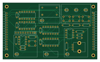
About the Clock PCB
Clock is an open source PCB design by benanderman, published on GitHub under the MIT license. It is a 2-layer board measuring 99.6 × 59.9 mm, with 37 components from 17 distinct parts.
Other key parts include the C2682068. By type, the board carries 8 capacitors, 8 resistors, 7 diodes, 6 ICs, 4 switches and 2 connectors.
From the project
An 8-bit CPU, made with TTL chips on custom, modular PCBs. Includes board designs, and Arduino code to program its instruction set and programs.
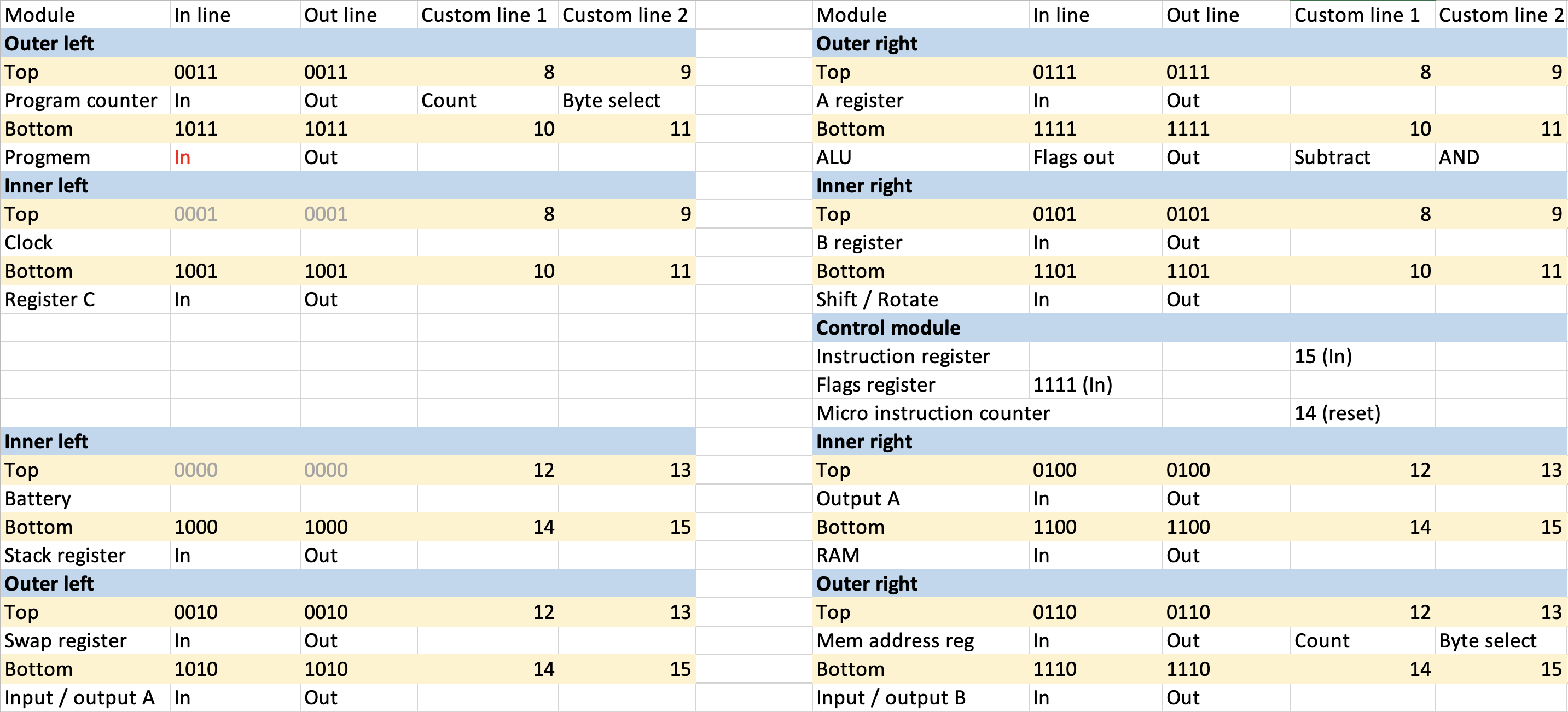
This is an 8-bit computer project, inspired by Ben Eater's 8-bit breadboard computer. It's made out of modular PCBs that plug into each other, and contain mostly 74HC-series chips (original 74LS). It runs code from an EEPROM (so it's only programmable from a computer), and has separate memory. It's meant to display what's happening, when running on a 555-timer or manually stepping, but also be capable enough to implement some sort of game, when using an oscillator as a clock.
Main components on the Clock
Clock bill of materials (BOM)
37 components, 17 distinct parts — part numbers from the project's BOM.
| Qty | Part | Footprint | Refs |
|---|---|---|---|
| 1 | C2682068 74HC02 | DIP-14_W7.62mm | U1 |
| 2 | C2682068 74HC32 | DIP-14_W7.62mm | U2, U6 |
| 1 | C2682068 74HC08 | DIP-14_W7.62mm | U4 |
| 2 | C2682068 LM555xN | DIP-8_W7.62mm | U5, U7 |
| 1 | ACO-xxxMHz | Oscillator_DIP-14 | X1 |
| 1 | CONN_01X12 Conn_01x16 | PinHeader_1x16_P2.54mm_Horizontal | J1 |
| 1 | Conn_01x16 | PinHeader_1x16_P2.54mm_Horizontal | J2 |
| 1 | 1M | Potentiometer_Bourns_PTV09A-1_Single_Vertical | RV1 |
| 4 | SW_Push | SW_PUSH_6mm | SW1, SW2, SW3, SW4 |
| 7 | C965793 LED | LED_D3.0mm_Clear | D1, D2, D3, D4, D5, D6, D7 |
| 2 | C307331 0.01uF | C_Disc_D4.3mm_W1.9mm_P5.00mm | C1, C3 |
| 1 | C307331 1uF | C_Disc_D4.3mm_W1.9mm_P5.00mm | C2 |
| 5 | C307331 0.1uF | C_Disc_D4.3mm_W1.9mm_P5.00mm | C4, C5, C6, C7, C8 |
| 3 | C25744 100k | R_Axial_DIN0207_L6.3mm_D2.5mm_P7.62mm_Horizontal | R1, R2, R3 |
| 3 | C25744 1k | R_Axial_DIN0207_L6.3mm_D2.5mm_P7.62mm_Horizontal | R4, R5, R6 |
| 1 | C25744 1M | R_Axial_DIN0207_L6.3mm_D2.5mm_P7.62mm_Horizontal | R7 |
| 1 | 1k | R_Array_SIP9 | RN1 |
Clock design files
The KiCad project lives in the benanderman/spork-8 repository on GitHub; these links point at the commit this page was built from.
- LayoutClock/Clock.kicad_pcb
- SchematicClock/Clock.kicad_sch
- BOMScreen/Screen-BOM.csv
Clock: common questions
How big is the Clock PCB?
The Clock measures 99.6 × 59.9 mm, has 2 copper layers and is 1.6 mm thick.
How many components are on the Clock?
37 components, from 17 distinct parts, with part numbers taken from the project's own BOM. The full bill of materials is listed on this page.
Where can I download the Clock design files?
From the benanderman/spork-8 repository on GitHub, which has the KiCad layout, the schematic and the BOM; the links under Design files point to each one.
Can I use the Clock design in my own project?
Yes, under the terms of its MIT license, which benanderman chose for the repository.
More boards in spork-8
Screen
65.3 × 99.4 mm452 parts2LMIT54 AVR/Arduino
Programmer
99.6 × 59.9 mm106 parts2LMIT54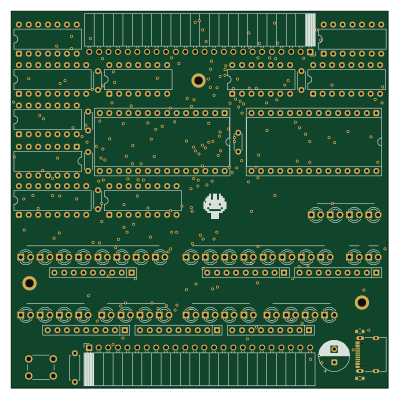
Control Module
99.6 × 99.6 mm70 parts4LMIT54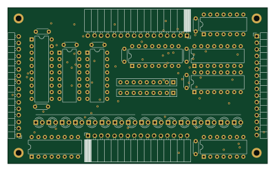
Counter
99.6 × 59.9 mm40 parts2LMIT54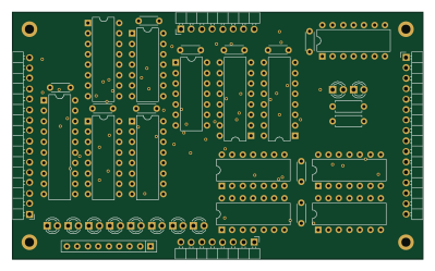
ALU
99.6 × 59.9 mm40 parts2LMIT54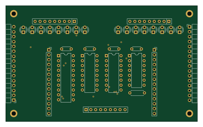
IO
99.6 × 59.9 mm32 parts2LMIT54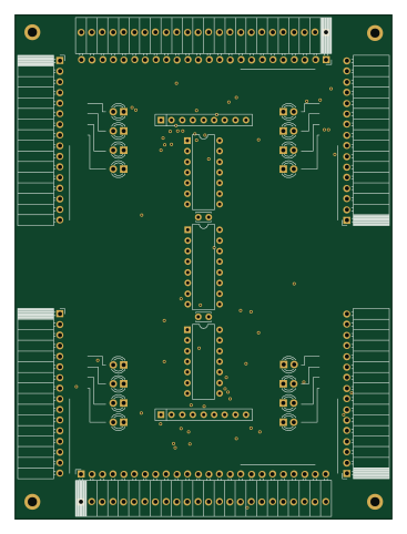
Bus
89.9 × 120.4 mm31 parts4LMIT54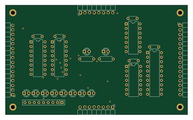
Shift
99.6 × 59.9 mm27 parts2LMIT54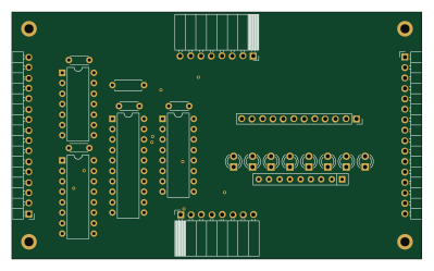
Register
99.6 × 59.9 mm23 parts2LMIT54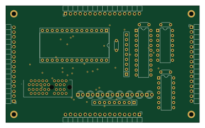
RAM
99.6 × 59.9 mm23 parts2LMIT54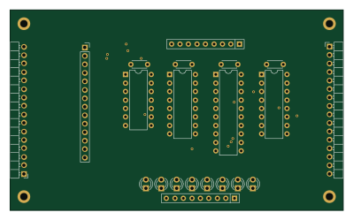
Input
99.6 × 59.9 mm21 parts2LMIT54