
Ammeter clock

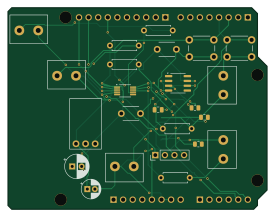
About the Ammeter clock PCB
Ammeter clock is an open source PCB design by benhg, published on GitHub. It is a 2-layer board measuring 68.6 × 53.3 mm, with 28 components from 26 distinct parts.
Other key parts include the MCP4728-E/UN, OPA197IDR and KH-2.54FH-1X3P-H8.5. By type, the board carries 10 connectors, 8 resistors, 5 capacitors, 3 ICs and 2 switches.
From the project
This is an isolated successor to the built Rev F4 two-meter shield. Open ammeter-clock/ammeter-clock.kicadpro` here in KiCad 8. The root project is the Rev F4 baseline and is not replaced by Rev 2.
This is an isolated successor to the built Rev F4 two-meter shield. Open ammeter-clock/ammeter-clock.kicadpro` here in KiCad 8. The root project is the Rev F4 baseline and is not replaced by Rev 2.
- R10 (56 kΩ, 1%) and J10 (two-position 5 mm screw terminal) duplicate R3/J3. MCP4728 B / pin 7 drives R10 → J10 pin 1 (+); pin 2 is GND. - Hours remain on DAC D / pin 9; minutes remain on C / pin 8. A / pin 6 is unused. The old schematic's reversed channel names were corrected to match these pins. - J5 rotates 180° around its body center, with wire entry toward the board center, away from the…
Main components on the Ammeter clock
Ammeter clock bill of materials (BOM)
28 components, 26 distinct parts — part numbers from the project's BOM.
| Qty | Part | Footprint | Refs |
|---|---|---|---|
| 1 | MCP4728-E/UN Microchip | MSOP-10_3x3mm_P0.5mm | U1 |
| 1 | OPA197IDR OPA197ID Texas Instruments | SOIC-8_3.9x4.9mm_P1.27mm | U3 |
| 1 | KH-2.54FH-1X3P-H8.5 Pololu_U3V16F15 Kinghelm | Pololu_U3V16F15_Socket | U4 |
| 1 | SSQ-108-03-T-S UNO_R3_POWER Samtec | Uno_R3_Stackable_1x08 | J1 |
| 1 | JL301-50002U02 HOUR_0-15V JILN | JILN_JL301_2P_P5.00mm | J2 |
| 1 | JL301-50002U02 MINUTE_100uA JILN | JILN_JL301_2P_P5.00mm | J3 |
| 1 | JL301-50002U02 HOUR_EXT_BUTTON JILN | JILN_JL301_2P_P5.00mm | J4 |
| 1 | JL301-50002U02 MIN_EXT_BUTTON JILN | JILN_JL301_2P_P5.00mm | J5 |
| 1 | DS1021-1X4SF11-B RTC_I2C_OPTION Connfly | PinHeader_1x04_P2.54mm_Vertical | J6 |
| 1 | SSQ-106-03-G-S UNO_R3_ANALOG Samtec | Uno_R3_Stackable_1x06 | J7 |
| 1 | SSQ-108-03-T-S UNO_R3_D0_D7 Samtec | Uno_R3_Stackable_1x08 | J8 |
| 1 | SSQ-110-03-T-S UNO_R3_D8_SCL Samtec | Uno_R3_Stackable_1x10 | J9 |
| 1 | JL301-50002U02 SECOND_100uA JILN | JILN_JL301_2P_P5.00mm | J10 |
| 1 | TS-1102-5516 HOUR_SET_NO SOFNG | SW_PUSH_6mm | SW1 |
| 1 | TS-1102-5516 MIN_SET_NO SOFNG | SW_PUSH_6mm | SW2 |
| 1 | CT4-0805B104K500F3 100n FH (Guangdong Fenghua Advanced Tech) | FH_CT4_0805_P5.08mm | C1 |
| 1 | CT4-0805B104K500F3 100n 25V FH (Guangdong Fenghua Advanced Tech) | FH_CT4_0805_P5.08mm | C3 |
| 1 | RXW100M1EBK-0511 10u 25V Lelon | CP_Radial_D5.0mm_P2.00mm | C4 |
| 1 | 50YXM33MEFR6.3X11 33u 10V Rubycon | CP_Radial_D6.3mm_P2.50mm | C5 |
| 1 | CL21C102JBCNNNC 1n C0G 25V Samsung Electro-Mechanics | C_0805_2012Metric | C6 |
Show 6 more
| Qty | Part | Footprint | Refs |
|---|---|---|---|
| 1 | PTFR0805B22K0N9 22k 0.1% RESI | R_0805_2012Metric | R1 |
| 1 | PTFR0805B10K0N9 10k 0.1% RESI | R_0805_2012Metric | R2 |
| 2 | MFR50SFTE52-56K 56k 1% Yageo | R_Axial_DIN0207_L6.3mm_D2.5mm_P7.62mm_Horizontal | R3, R10 |
| 2 | MFR-25FTE52-4K7 4.7k YAGEO | R_Axial_DIN0207_L6.3mm_D2.5mm_P7.62mm_Horizontal | R4, R5 |
| 1 | MFR-25FTF52-47R 47R 1% Yageo | R_Axial_DIN0207_L6.3mm_D2.5mm_P7.62mm_Horizontal | R6 |
| 1 | 0805W8F4701T5E 4.7k 1% UNI-ROYAL | R_0805_2012Metric | R9 |
Ammeter clock design files
The KiCad project lives in the benhg/ammeter-clock repository on GitHub; these links point at the commit this page was built from.
Ammeter clock: common questions
How big is the Ammeter clock PCB?
The Ammeter clock measures 68.6 × 53.3 mm, has 2 copper layers and is 1.6 mm thick.
How many components are on the Ammeter clock?
28 components, from 26 distinct parts, with part numbers taken from the project's own BOM. The full bill of materials is listed on this page.
Where can I download the Ammeter clock design files?
From the benhg/ammeter-clock repository on GitHub, which has the KiCad layout, the schematic and the BOM; the links under Design files point to each one.
Can I use the Ammeter clock design in my own project?
The repository has no license, so all rights stay with benhg. Use it as a reference, and ask the author before reusing the design.