
Hw fan switch

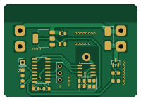
About the Hw fan switch PCB
Hw fan switch is an open source PCB design by burgrp, published on GitHub. It is a 2-layer board measuring 50 × 35 mm, with 23 components from 20 distinct parts.
Other key parts include the LM1117MP-3.3, PAN2110P0AA, PY32F003W1xSx and 31mm. By type, the board carries 6 capacitors, 5 connectors, 3 ICs, 3 resistors, 2 crystals and 2 diodes.
It belongs with the iot & wireless designs in this gallery.
From the project
12V DC Fan switch based on ESP8266
A small, wirelessly-controlled 12 V DC fan switch. It drives a fan with a variable PWM duty cycle and is controlled over a BLE long-range radio link, making it part of the Bleriot node network.
The board is built around a Puya PY32F003 Cortex-M0+ microcontroller with a PAN211x radio, and the firmware is written in Go and compiled with TinyGo.
- Variable-speed fan control via hardware PWM (TIM14CH1 on PB1). - 50 kHz PWM carrier, above the audible range to avoid switching noise. - Configurable low-speed handling: - Low-duty threshold — below this duty the fan is treated as stopped and the…
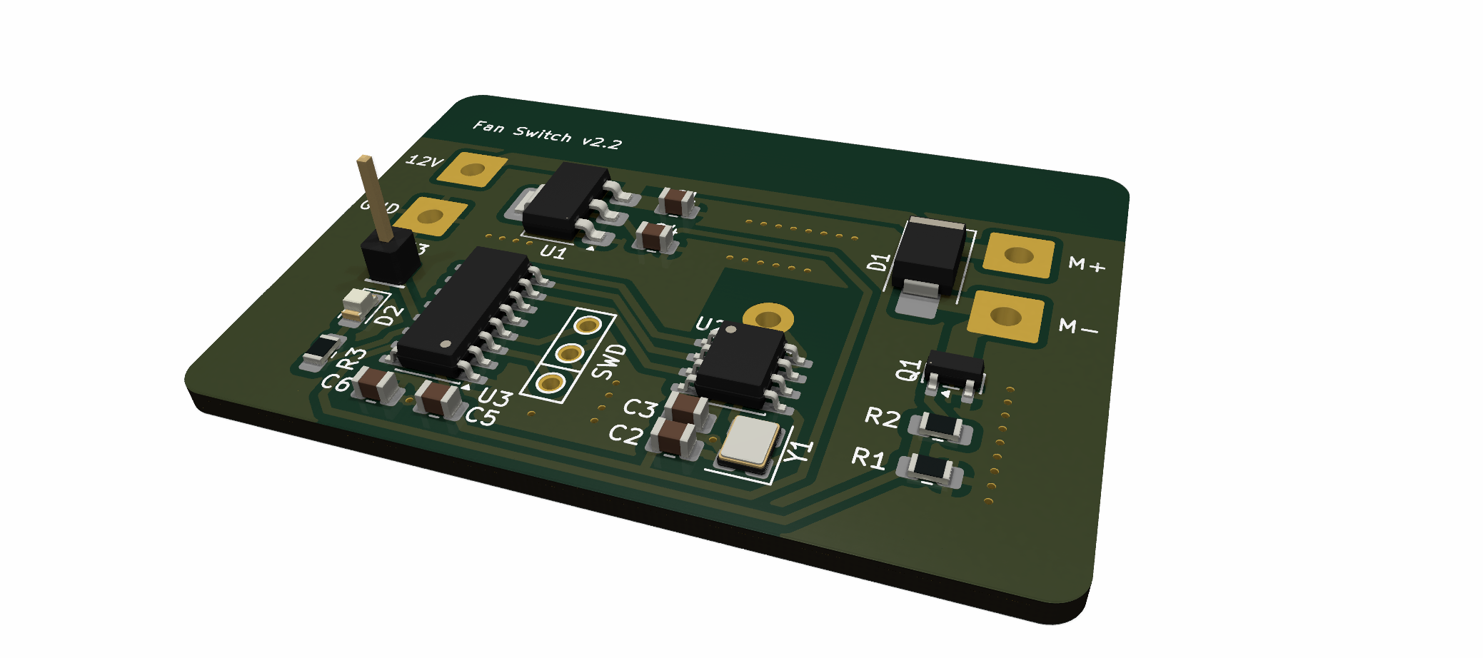
Main components on the Hw fan switch
Hw fan switch bill of materials (BOM)
23 components, 20 distinct parts.
| Qty | Part | Footprint | Refs |
|---|---|---|---|
| 1 | LM1117MP-3.3 | SOT-223-3_TabPin2 | U1 |
| 1 | PAN2110P0AA | SOIC-8_3.9x4.9mm_P1.27mm | U2 |
| 1 | PY32F003W1xSx | SOIC-16_3.9x9.9mm_P1.27mm | U3 |
| 1 | 31mm | Wire antena 2.4GHz | A1 |
| 1 | AO3400A | SOT-23 | Q1 |
| 1 | SWD | SWD | X1 |
| 1 | 16MHz | Crystal_SMD_3225-4Pin_3.2x2.5mm | Y1 |
| 1 | 12V | SolderWire-1sqmm_1x01_D1.4mm_OD3.9mm | J1 |
| 1 | GND | SolderWire-1sqmm_1x01_D1.4mm_OD3.9mm | J2 |
| 1 | TX | PinHeader_1x01_P2.54mm_Vertical | J3 |
| 1 | M+ | SolderWire-1sqmm_1x01_D1.4mm_OD3.9mm | J4 |
| 1 | M- | SolderWire-1sqmm_1x01_D1.4mm_OD3.9mm | J5 |
| 1 | SK22 | D_SMB_Handsoldering | D1 |
| 1 | LED | LED_0805_2012Metric_Pad1.15x1.40mm_HandSolder | D2 |
| 2 | 10u | C_0805_2012Metric | C1, C4 |
| 1 | 1u | C_0805_2012Metric | C2 |
| 3 | 100n | C_0805_2012Metric | C3, C5, C6 |
| 1 | 10k | R_0805_2012Metric_Pad1.20x1.40mm_HandSolder | R1 |
| 1 | 100 | R_0805_2012Metric_Pad1.20x1.40mm_HandSolder | R2 |
| 1 | 330R | R_0805_2012Metric_Pad1.20x1.40mm_HandSolder | R3 |
Hw fan switch design files
The KiCad project lives in the burgrp/hw-fan-switch repository on GitHub; these links point at the commit this page was built from.
- Layoutboard/fan-switch.kicad_pcb
- Schematicboard/fan-switch.kicad_sch
Hw fan switch: common questions
How big is the Hw fan switch PCB?
The Hw fan switch measures 50 × 35 mm, has 2 copper layers and is 1.6 mm thick.
How many components are on the Hw fan switch?
23 components, from 20 distinct parts. The full bill of materials is listed on this page.
Where can I download the Hw fan switch design files?
From the burgrp/hw-fan-switch repository on GitHub, which has the KiCad layout and the schematic; the links under Design files point to each one.
Can I use the Hw fan switch design in my own project?
The repository has no license, so all rights stay with burgrp. Use it as a reference, and ask the author before reusing the design.
Similar boards
EinkPDA screen
TalismanDesign
95 × 54 mm27 parts2LApache-2.02.0k
RPi RM0 WiFi/Bluetooth Module
schlae
11.1 × 14 mm76 parts6LNo license1.0k
L0 USB
Luos-io
20.3 × 15.3 mm19 parts2LMIT547
Breakout board
26.7 × 27.9 mm29 parts2LMIT547
Stm32f0 disco Luos shield
55.9 × 99.1 mm26 parts2LMIT547
L0 USBA
20.3 × 15.3 mm19 parts2LMIT547