
BioSmartSense-IoT

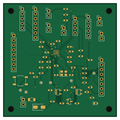
About the BioSmartSense-IoT PCB
BioSmartSense-IoT is an open source PCB design by C12isme945, published on GitHub under the Apache-2.0 license. It is a 4-layer board measuring 60 × 60 mm, with 61 components from 37 distinct parts.
Other key parts include the AD5940BCBZ-RL7, ADP150AUJZ-3.3-R7 and MAX809TEUR+T. By type, the board carries 26 capacitors, 14 resistors, 7 connectors, 5 jumpers, 4 ICs and 2 diodes.
It belongs with the iot & wireless designs in this gallery.
From the project
Portable IoT Electrochemical Biosensor & Edge AI Platform for Real-Time Water Quality & Bio-Diagnostics (Hyperbloom September Hackathon 2026)
Water pollution, heavy metal toxicity (Lead $Pb^{2+}$, Cadmium $Cd^{2+}$), and delayed physiological biomarker diagnostics disproportionately impact vulnerable populations. Traditional laboratory electrochemical workstations (potentiostats / impedance analyzers) cost upwards of $5,000–$15,000 USD, requiring bulky benchtop setups and trained operators.
BioSmartSense-IoT bridges this gap: 1. Custom Open Hardware: An ultra-compact, JLCPCB-manufactured 4-layer HDI PCB powered by the Analog Devices AD5940 precision Analog Front End (AFE) with standard Screen Printed Electrode (SPE) sockets. 2.…
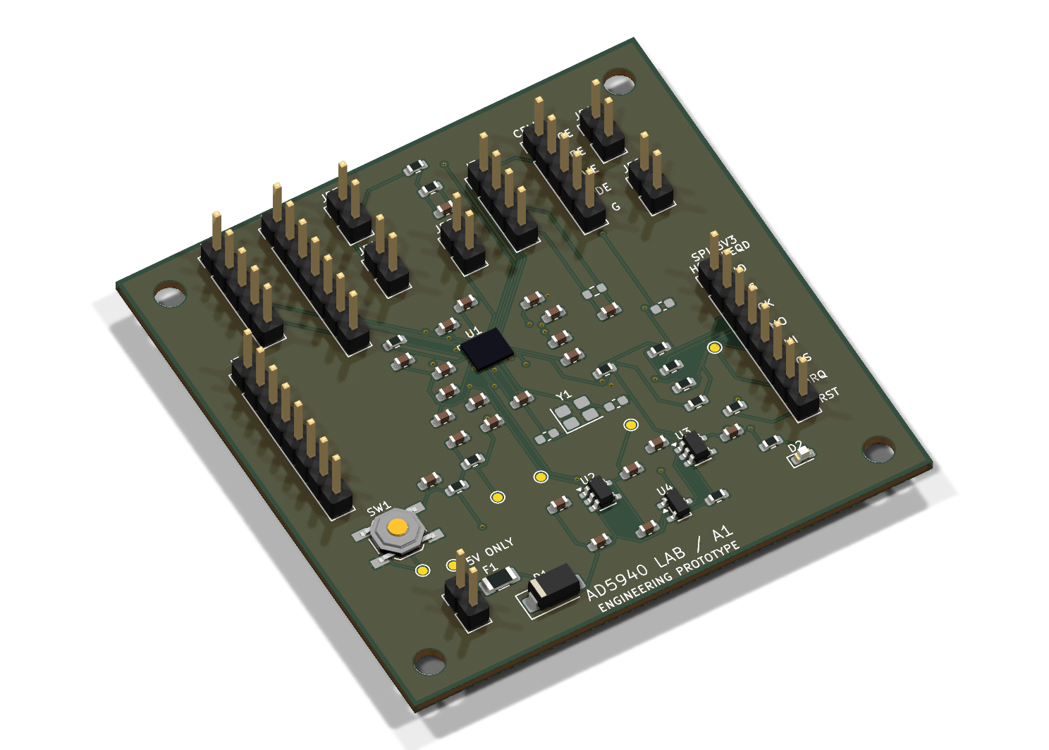
Main components on the BioSmartSense-IoT
BioSmartSense-IoT bill of materials (BOM)
61 components, 37 distinct parts — part numbers from the project's BOM.
| Qty | Part | Footprint | Refs |
|---|---|---|---|
| 1 | AD5940BCBZ-RL7 | AD5940_WLCSP56_0.4mm | U1 |
| 2 | ADP150AUJZ-3.3-R7 | SOT-23-5 | U2, U3 |
| 1 | MAX809TEUR+T | SOT-23 | U4 |
| 1 | 16MHz CL=8pF OPTION | Crystal_SMD_3225-4Pin_3.2x2.5mm | Y1 |
| 1 | 5V INPUT 4.75-5.25V | PinHeader_1x02_P2.54mm_Vertical | J1 |
| 1 | 3V3 SPI HOST | PinHeader_1x08_P2.54mm_Vertical | J2 |
| 1 | GPIO EXPANSION | PinHeader_1x08_P2.54mm_Vertical | J3 |
| 1 | AFE EXPANSION | PinHeader_1x05_P2.54mm_Vertical | J4 |
| 1 | ADC EXPANSION | PinHeader_1x07_P2.54mm_Vertical | J5 |
| 1 | CELL CE RE WE DE GND | PinHeader_1x05_P2.54mm_Vertical | J6 |
| 1 | EXTERNAL TIA | PinHeader_1x04_P2.54mm_Vertical | J7 |
| 1 | PTC 100mA | Fuse_1206_3216Metric | F1 |
| 1 | 2-WIRE SHORT CE-RE | PinHeader_1x02_P2.54mm_Vertical | JP1 |
| 1 | SHORT WE-DE IF MODE REQUIRES | PinHeader_1x02_P2.54mm_Vertical | JP2 |
| 1 | DUMMY CE | PinHeader_1x02_P2.54mm_Vertical | JP3 |
| 1 | DUMMY RE | PinHeader_1x02_P2.54mm_Vertical | JP4 |
| 1 | DUMMY WE | PinHeader_1x02_P2.54mm_Vertical | JP5 |
| 1 | RESET | SW_SPST_TL3342 | SW1 |
| 1 | SS14 | D_SMA | D1 |
| 1 | GREEN | LED_0603_1608Metric | D2 |
Show 17 more
| Qty | Part | Footprint | Refs |
|---|---|---|---|
| 9 | 100NF 100nF | C_0603_1608Metric | C1, C2, C4, C6, C13, C14, C15, C25 +1 |
| 3 | 10UF 10uF | C_0603_1608Metric | C3, C5, C20 |
| 3 | 1UF 1uF | C_0603_1608Metric | C7, C21, C23 |
| 3 | 4.7UF 4.7uF | C_0603_1608Metric | C8, C22, C24 |
| 4 | 470NF 470nF | C_0603_1608Metric | C9, C10, C11, C12 |
| 1 | 220nF | C_0603_1608Metric | C17 |
| 2 | 6.8pF C0G | C_0603_1608Metric | C18, C19 |
| 1 | 100nF 5% | C_0603_1608Metric | C26 |
| 1 | 1k | R_0603_1608Metric | R1 |
| 1 | 10k 0.1% 10ppm | R_0603_1608Metric | R2 |
| 1 | 100k 0.1% | R_0603_1608Metric | R3 |
| 1 | 2.2K 2.2k | R_0603_1608Metric | R4 |
| 5 | 33R | R_0603_1608Metric | R5, R6, R7, R8, R9 |
| 2 | 10K 10k | R_0603_1608Metric | R10, R11 |
| 1 | 1k 0.1% | R_0603_1608Metric | R12 |
| 1 | 10k 0.1% | R_0603_1608Metric | R13 |
| 1 | 100K 100k | R_0603_1608Metric | R14 |
BioSmartSense-IoT design files
The KiCad project lives in the C12isme945/BioSmartSense-IoT repository on GitHub; these links point at the commit this page was built from.
BioSmartSense-IoT: common questions
How big is the BioSmartSense-IoT PCB?
The BioSmartSense-IoT measures 60 × 60 mm, has 4 copper layers and is 1.2 mm thick.
How many components are on the BioSmartSense-IoT?
61 components, from 37 distinct parts, with part numbers taken from the project's own BOM. The full bill of materials is listed on this page.
Where can I download the BioSmartSense-IoT design files?
From the C12isme945/BioSmartSense-IoT repository on GitHub, which has the KiCad layout, the schematic and the BOM; the links under Design files point to each one.
Can I use the BioSmartSense-IoT design in my own project?
Yes, under the terms of its Apache-2.0 license, which C12isme945 chose for the repository.
Similar boards

RPi RM0 WiFi/Bluetooth Module
schlae
11.1 × 14 mm76 parts6LNo license1.0k
L0 IMU MPU9250
Luos-io
20.3 × 15.2 mm7 parts2LMIT547
L0 USBA
20.3 × 15.3 mm19 parts2LMIT547
L0 Controller motor
20.3 × 15.3 mm11 parts2LMIT547
L0 Dynamixel
20.3 × 15.2 mm15 parts2LMIT547
L0 stepper driver
20.3 × 15.2 mm18 parts2LMIT547