
USB Keypad

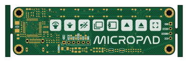
About the USB Keypad PCB
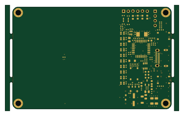
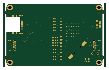
USB Keypad is an open source STM32 PCB design by CDFER, published on GitHub under the Custom license license. It is a 2-layer board measuring 93 × 27 mm, with 77 components from 32 distinct parts.
Its main chip is the MCU 72MHz STM32F103C8T6, from the STM32 family. Other key parts include the 8MHz 20pF ±10ppm. By type, the board carries 28 capacitors, 26 resistors, 9 switches, 7 LEDs, 2 ICs and 1 connector.
It belongs with the keyboards designs in this gallery.
From the project
Showcasing a collection of functional PCB business cards, each demonstrating a unique embedded electronics project.
The USB MicroPad is an 8-button macro pad for various applications, from productivity shortcuts to copy and paste macros. It's implemented as a USB HID keyboard and HID media consumer controller, ensuring compatibility with major operating systems without additional drivers.
8 programmable buttons USB-C connector 3.3V LDO regulator with low dropout voltage STM32F103C8T6 microcontroller with 72MHz CPU * Compatible with most operating systems as a USB HID device
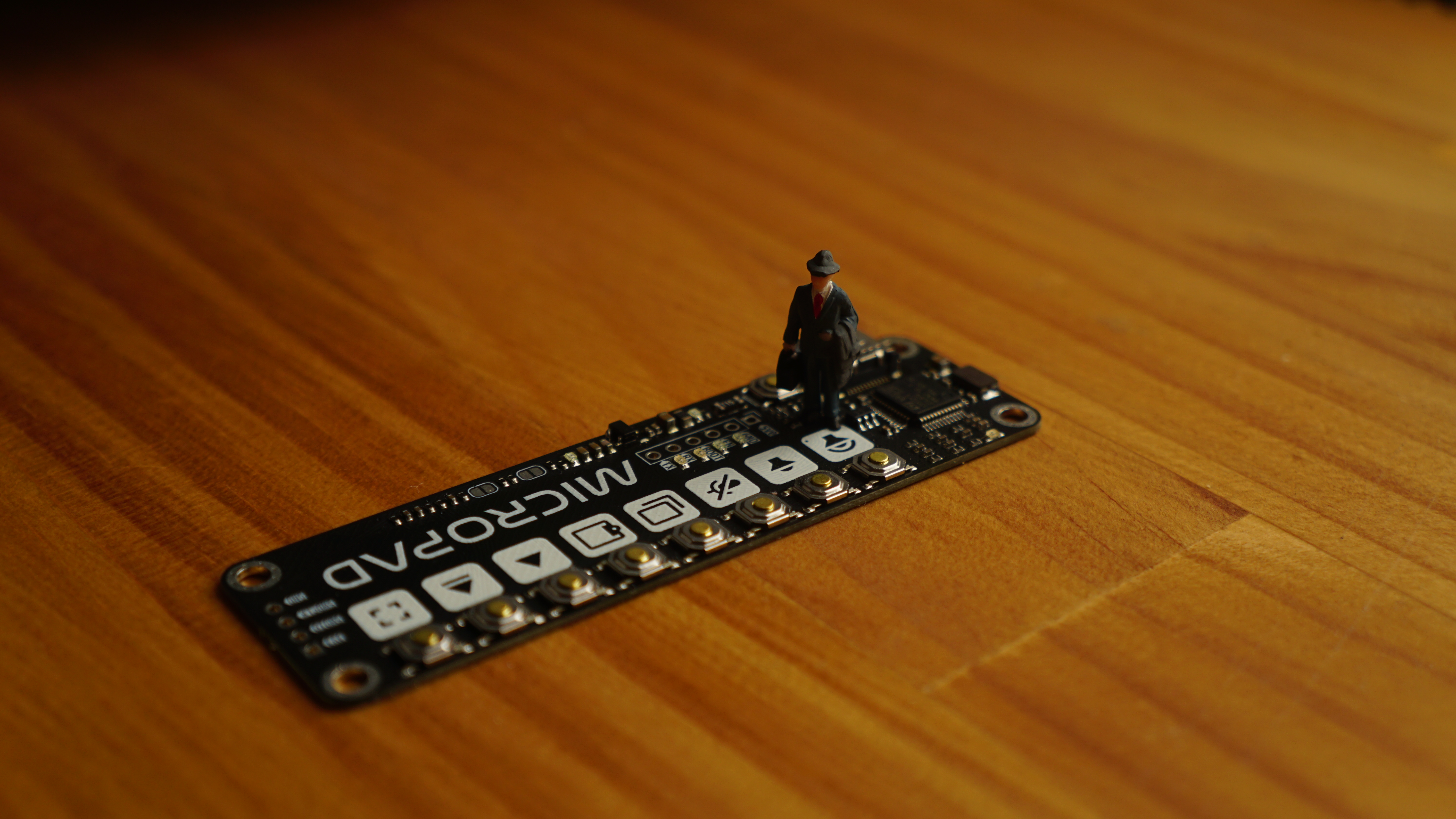
Main components on the USB Keypad
USB Keypad bill of materials (BOM)
77 components, 32 distinct parts.
| Qty | Part | Footprint | Refs |
|---|---|---|---|
| 1 | MCU 72MHz STM32F103C8T6 | LQFP-48_L7.0-W7.0-P0.50-LS9.0-BL | U1 |
| 1 | 8MHz 20pF ±10ppm | CRYSTAL-SMD_L5.0-W3.2 | U2 |
| 1 | USB_C_Receptacle | TYPE-C-SMD_C9900025773 | J2 |
| 1 | SRV05 | SOT-23-6_L2.9-W1.6-P0.95-LS2.8-BR | ESD1 |
| 1 | 1.5A Resettable Fuse | Fuse_1206_3216Metric | F1 |
| 1 | LDO 3.3V 200mA XC6206P332MR | SOT-23-3_L2.9-W1.6-P1.90-LS2.8-BR | LDO1 |
| 9 | Button SPST 50mA 12V | SW-SMD_4P-L5.1-W5.1-P3.70-LS6.5-TL-2 | SW1, SW2, SW3, SW4, SW5, SW6, SW7, SW8 +1 |
| 4 | 0603,Red | LED0603 | LED1, LED2, LED6, LED7 |
| 3 | 0603,Yellow | LED0603 | LED3, LED4, LED5 |
| 1 | 0805,800mA | 0805_2012Metric | FB1 |
| 2 | 0402CG200J500NT 0402,20pF,50V,C0G | 0402_1005Metric | C1, C6 |
| 4 | CL05B104KO5NNNC 100nF | 0402_1005Metric | C2, C4, C11, C16 |
| 1 | CL21B105KBFNNNE 0805,1uF,50V,X7R | 0805_2012Metric | C3 |
| 9 | CL05A105KA5NQNC 0402,1uF,25V,X5R | 0402_1005Metric | C5, C30, C31, C34, C35, C36, C37, C38 +1 |
| 1 | CL05C331JB5NNNC 0402,330pF,50V,C0G | 0402_1005Metric | C7 |
| 2 | CL05A475MP5NRNC 0402,4.7uF,10V,X5R | 0402_1005Metric | C8, C18 |
| 4 | CL05C331JB5NNNC 330pF | 0402_1005Metric | C9, C10, C15, C17 |
| 2 | CL10B474KA8NNNC 0603,470nF,25V,X7R | 0603_1608Metric | C12, C14 |
| 1 | CL10C331JB8NNNC 0603,330pF,50V,C0G | 0603_1608Metric | C13 |
| 1 | CL05B103KB5NNNC 10nF | 0402_1005Metric | C32 |
Show 12 more
| Qty | Part | Footprint | Refs |
|---|---|---|---|
| 1 | CL21B105KBFNNNE 1uF | 0805_2012Metric | C33 |
| 1 | 0402WGF1004TCE 0402,1M | 0402_1005Metric | R1 |
| 2 | 0402WGF220JTCE 0402,22 | 0402_1005Metric | R2, R3 |
| 1 | 0402WGF4701TCE 0402,4.7k | 0402_1005Metric | R4 |
| 9 | 0402WGF1002TCE 0402,10k | 0402_1005Metric | R5, R6, R19, R20, R21, R24, R26, R27 +1 |
| 1 | 0402WGF1500TCE 0402,150 | 0402_1005Metric | R7 |
| 2 | 0402WGF1003TCE 0402,100k | 0402_1005Metric | R8, R9 |
| 2 | 0402WGF1001TCE 0402,1k | 0402_1005Metric | R10, R11 |
| 2 | 0402WGF6800TCE 0402,680 | 0402_1005Metric | R12, R17 |
| 2 | 0402WGF5101TCE 0402,5.1k | 0402_1005Metric | R13, R14 |
| 3 | 0402WGF1201TCE 0402,1.2k | 0402_1005Metric | R15, R16, R22 |
| 1 | 0402WGF3300TCE 0402,330 | 0402_1005Metric | R18 |
USB Keypad design files
The KiCad project lives in the CDFER/Business-Cards repository on GitHub; these links point at the commit this page was built from.
USB Keypad: common questions
What microcontroller does the USB Keypad use?
The USB Keypad is built around the MCU 72MHz STM32F103C8T6, from the STM32 family.
How big is the USB Keypad PCB?
The USB Keypad measures 93 × 27 mm, has 2 copper layers and is 0.99 mm thick.
How many components are on the USB Keypad?
77 components, from 32 distinct parts. The full bill of materials is listed on this page.
Where can I download the USB Keypad design files?
From the CDFER/Business-Cards repository on GitHub, which has the KiCad layout and the schematic; the links under Design files point to each one.
Can I use the USB Keypad design in my own project?
It is published under Custom license, which limits how it may be reused; read the license before building on it.
Can I test firmware for the USB Keypad without the hardware?
Yes. HardLabs builds a simulation of the board from its netlist and BOM, so you can run and debug STM32 firmware against it before you order a PCB.
More boards in Business-Cards
Similar boards
 STM32
STM32LumenPnP Motherboard
opulo-inc
149 × 95 mm296 parts4LCC-BY-SA-4.03.7k STM32
STM32AxxSolder
AxxAxx
39 × 82.5 mm122 parts2LGPL-3.01.7k STM32
STM32AIOC
skuep
21 × 31.5 mm47 parts2LMIT1.4k STM32
STM32Ferris
pierrechevalier83
208.8 × 86.8 mm102 parts2LSHL-2.11.3k STM32
STM32176 pin board
rusefi
61.8 × 73.2 mm76 parts2LGPL-3.01.2k STM32
STM32Brain board STM32F407
61.8 × 73.2 mm69 parts2LGPL-3.01.2k