
Basic DSP V0 1

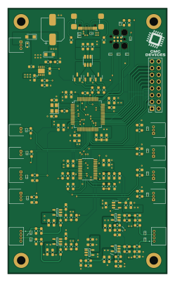
About the Basic DSP V0 1 PCB
Basic DSP V0 1 is an open source STM32 PCB design by CoderCallender, published on GitHub. It is a 6-layer board measuring 60 × 100 mm, with 160 components from 40 distinct parts.
Its main chip is the STM32F415RGT6, from the STM32 family. Other key parts include the CS4270-CZZR, TLV76733QWDRBRQ1, NCP718BSN500T1G and TLV9161IDBVR. By type, the board carries 61 capacitors, 49 resistors, 24 diodes, 13 connectors, 9 ICs and 3 transistors.
From the project
Digital Signal Processing Hardware and Firmware
Main components on the Basic DSP V0 1
Basic DSP V0 1 bill of materials (BOM)
160 components, 40 distinct parts — part numbers from the project's BOM.
| Qty | Part | Footprint | Refs |
|---|---|---|---|
| 1 | STM32F415RGT6 STM32F415RGTx | LQFP-64_10x10mm_P0.5mm | U1 |
| 1 | CS4270-CZZR CS4270 | TSSOP-24_4.4x7.8mm_P0.65mm | U2 |
| 1 | TLV76733QWDRBRQ1 | SON65P300X300X100-9N-D | U3 |
| 1 | NCP718BSN500T1G | SOT-23-5 | U5 |
| 5 | TLV9161IDBVR | SOT95P280X145-5N | U6, U7, U8, U9, U10 |
| 3 | AO3400A | SOT-23 | Q1, Q2, Q3 |
| 1 | ABM8G-24.000MHZ-18-D2Y-T3 | Crystal_SMD_Abracon_ABM8G-4Pin_3.2x2.5mm | Y1 |
| 7 | 53048-0310 | SHDRRA3W35P0X125_1X3_550X550X350P | J1, J2, J3, J7, J8, J9, J10 |
| 1 | USB_C_Receptacle_USB2.0_16P | USB_C_Receptacle_GCT_USB4110 | J4 |
| 2 | 53048-0410 | 530480410 | J6, J11 |
| 2 | 53048-0210 | SHDRRA2W35P0X125_1X2_425X550X350P | J14, J15 |
| 1 | Conn_02x08_Odd_Even | PinSocket_2x08_P2.54mm_Vertical | J16 |
| 2 | PMEG4030ER | Nexperia_CFP3_SOD-123W | D1, D2 |
| 1 | ESD5Z12T1G ESD5Z12T1G/T5G | D_SOD-523 | D3 |
| 13 | ESD9B3.3ST5G | D_SOD-923 | D4, D8, D10, D11, D12, D13, D16, D17 +5 |
| 7 | ESD9B5.0ST5G | D_SOD-923 | D6, D9, D14, D15, D21, D24, D26 |
| 1 | SMLVN6RGB1W1 SMLVN6RGB | LED_ROHM_SMLVN6 | D23 |
| 23 | 0603B104M250NT 100n | C_0603_1608Metric_Pad1.08x0.95mm_HandSolder | C1, C3, C5, C6, C8, C12, C14, C23 +15 |
| 15 | 0603B225K250NT 2u2 | C_0603_1608Metric_Pad1.08x0.95mm_HandSolder | C2, C4, C13, C51, C52, C65, C66, C67 +7 |
| 6 | CL10A106MA8NRNC 10u | C_0603_1608Metric_Pad1.08x0.95mm_HandSolder | C7, C9, C27, C34, C43, C48 |
Show 20 more
| Qty | Part | Footprint | Refs |
|---|---|---|---|
| 2 | CGA0603X5R226M160JT 22u | C_0603_1608Metric_Pad1.08x0.95mm_HandSolder | C15, C49 |
| 1 | CK1V221M-CRF10 220uF | CP_Elec_8x10.5 | C16 |
| 4 | CGA3E2X8R2A103KT0Y0H 10n | C_0603_1608Metric_Pad1.08x0.95mm_HandSolder | C26, C33, C42, C47 |
| 4 | 0603N221J500CT 220p | C_0603_1608Metric_Pad1.08x0.95mm_HandSolder | C28, C29, C36, C38 |
| 2 | GCJ188R71H102KA01D 1n | C_0603_1608Metric_Pad1.08x0.95mm_HandSolder | C44, C50 |
| 2 | RF18N180F500CT 18p | C_0603_1608Metric_Pad1.08x0.95mm_HandSolder | C59, C60 |
| 2 | CL10A106MA8NRNC 10uF | C_0603_1608Metric | C73, C74 |
| 12 | WR06X33R0FTL 33R | R_0603_1608Metric_Pad0.98x0.95mm_HandSolder | R1, R12, R13, R21, R23, R26, R27, R38 +4 |
| 2 | 0603WAF2201T5E 2k2 | R_0603_1608Metric_Pad0.98x0.95mm_HandSolder | R2, R3 |
| 6 | 0603WAF1002T5E 10K | R_0603_1608Metric_Pad0.98x0.95mm_HandSolder | R4, R5, R6, R31, R37, R51 |
| 1 | 0603WAF0000T5E 0R | R_0603_1608Metric_Pad0.98x0.95mm_HandSolder | R7 |
| 6 | RC0603FR-0747KL 47k | R_0603_1608Metric_Pad0.98x0.95mm_HandSolder | R8, R9, R10, R32, R36, R50 |
| 1 | 0603WAF100JT5E 0R | R_0603_1608Metric_Pad0.98x0.95mm_HandSolder | R11 |
| 6 | 0603WAF1004T5E 1M | R_0603_1608Metric_Pad0.98x0.95mm_HandSolder | R14, R17, R20, R25, R28, R33 |
| 4 | RC0603FR-07100RL 100R | R_0603_1608Metric_Pad0.98x0.95mm_HandSolder | R15, R22, R30, R35 |
| 4 | 0603WAJ0102T5E 1K | R_0603_1608Metric_Pad0.98x0.95mm_HandSolder | R16, R24, R29, R34 |
| 2 | 0603WAF5101T5E 5k1 | R_0603_1608Metric_Pad0.98x0.95mm_HandSolder | R39, R40 |
| 2 | RC0603FR-07100KL 100K | R_0603_1608Metric_Pad0.98x0.95mm_HandSolder | R41, R42 |
| 2 | 0603WAF1800T5E 180R | R_0603_1608Metric_Pad0.98x0.95mm_HandSolder | R44, R46 |
| 1 | 0603WAF2700T5E 270R | R_0603_1608Metric_Pad0.98x0.95mm_HandSolder | R45 |
Basic DSP V0 1 design files
The KiCad project lives in the CoderCallender/DSP_Projects repository on GitHub; these links point at the commit this page was built from.
Basic DSP V0 1: common questions
What microcontroller does the Basic DSP V0 1 use?
The Basic DSP V0 1 is built around the STM32F415RGT6, from the STM32 family.
How big is the Basic DSP V0 1 PCB?
The Basic DSP V0 1 measures 60 × 100 mm, has 6 copper layers and is 1.6 mm thick.
How many components are on the Basic DSP V0 1?
160 components, from 40 distinct parts, with part numbers taken from the project's own BOM. The full bill of materials is listed on this page.
Where can I download the Basic DSP V0 1 design files?
From the CoderCallender/DSP_Projects repository on GitHub, which has the KiCad layout, the schematic and the BOM; the links under Design files point to each one.
Can I use the Basic DSP V0 1 design in my own project?
The repository has no license, so all rights stay with CoderCallender. Use it as a reference, and ask the author before reusing the design.
Can I test firmware for the Basic DSP V0 1 without the hardware?
Yes. HardLabs builds a simulation of the board from its netlist and BOM, so you can run and debug STM32 firmware against it before you order a PCB.
More boards in DSP_Projects
Similar boards
 STM32
STM32LumenPnP Motherboard
opulo-inc
149 × 95 mm296 parts4LCC-BY-SA-4.03.7k STM32
STM32AxxSolder
AxxAxx
39 × 82.5 mm122 parts2LGPL-3.01.7k STM32
STM32AIOC
skuep
21 × 31.5 mm47 parts2LMIT1.4k STM32
STM32Ferris
pierrechevalier83
208.8 × 86.8 mm102 parts2LSHL-2.11.3k STM32
STM32176 pin board
rusefi
61.8 × 73.2 mm76 parts2LGPL-3.01.2k STM32
STM32Brain board STM32F407
61.8 × 73.2 mm69 parts2LGPL-3.01.2k