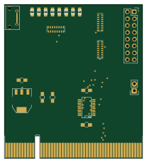
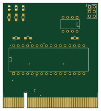
Cpu

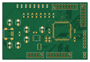
About the Cpu PCB
Cpu is an open source PCB design by depletionmode, published on GitHub. It is a 2-layer board measuring 76.2 × 50.8 mm, with 58 components from 29 distinct parts.
Other key parts include the EPCS1, LMS1585/7, LM1084IS-3.3/NOPB and EP1C3T100. By type, the board carries 25 capacitors, 10 resistors, 8 diodes, 7 connectors, 4 ICs and 2 inductors.
From the project
Then run kernel/debug.sh. The guest display is embedded by default; use kernel/debug.sh --display:window for the standalone SDL window. Terminal graphics and color treatment can be selected explicitly:
Then run kernel/debug.sh. The guest display is embedded by default; use kernel/debug.sh --display:window for the standalone SDL window. Terminal graphics and color treatment can be selected explicitly:
Inside the debugger, :display embedded|window, :theme auto|dark|light, and :gfx auto|kitty|half switch these modes without restarting. Pane borders can be dragged with the mouse to resize the layout. Press ? for the complete keymap and command reference.
Main components on the Cpu
Cpu bill of materials (BOM)
58 components, 29 distinct parts.
| Qty | Part | Footprint | Refs |
|---|---|---|---|
| 1 | EPCS1 | SOIC-8-N | U1 |
| 1 | LMS1585/7 | TO-263 | U2 |
| 1 | LM1084IS-3.3/NOPB | TO-263 | U3 |
| 1 | EP1C3T100 | TQFP-100_14x14mm_Pitch0.5mm | U4 |
| 1 | USB-MINI-B | USB_Mini-B | CON1 |
| 1 | PWR | Pin_Header_Straight_1x02 | P1 |
| 1 | BANK3 | Pin_Header_Straight_2x08 | P2 |
| 1 | BANK1 | Pin_Header_Straight_2x06 | P3 |
| 1 | BANK2 | Pin_Header_Straight_2x09 | P4 |
| 1 | BANK4 | Pin_Header_Straight_2x09 | P5 |
| 1 | CONN_6 | Pin_Header_Straight_1x06 | P6 |
| 1 | Si501AAA | DFN4-Si501 | OSC1 |
| 1 | 10K | R_Array_Convex_4x1206 | RP1 |
| 8 | LED | LED-0805 | D1, D2, D3, D4, D5, D6, D7, D8 |
| 2 | FILTER | R_0805_HandSoldering | FB1, FB2 |
| 1 | 10uF | C_0805_HandSoldering | C1 |
| 2 | 100uF | C_0805_HandSoldering | C2, C4 |
| 2 | 0.01uF | C_0805_HandSoldering | C3, C5 |
| 2 | 10uF | c_elec_4x4.5 | C6, C8 |
| 1 | 1000uF | c_elec_4x4.5 | C7 |
Show 9 more
| Qty | Part | Footprint | Refs |
|---|---|---|---|
| 10 | 0.2uF | C_0805_HandSoldering | C9, C10, C11, C12, C13, C14, C15, C16 +2 |
| 3 | 10uF | c_elec_4x5.3 | C19, C21, C22 |
| 1 | 1000uF | c_elec_4x5.3 | C20 |
| 1 | 0.1uF | C_0805 | C23 |
| 1 | 0.001uF | C_0805 | C24 |
| 1 | 10uF | C_0805 | C25 |
| 1 | 10M | R_0805_HandSoldering | R1 |
| 1 | 24.9 | R_0805_HandSoldering | R2 |
| 8 | 270 | R_0805_HandSoldering | R3, R4, R5, R6, R7, R8, R9, R10 |
Cpu design files
The KiCad project lives in the depletionmode/cupc8 repository on GitHub; these links point at the commit this page was built from.
- Layoutpcb/fpga/cpu.kicad_pcb
Cpu: common questions
How big is the Cpu PCB?
The Cpu measures 76.2 × 50.8 mm, has 2 copper layers and is 1.6 mm thick.
How many components are on the Cpu?
58 components, from 29 distinct parts. The full bill of materials is listed on this page.
Where can I download the Cpu design files?
From the depletionmode/cupc8 repository on GitHub, which has the KiCad layout; the links under Design files point to each one.
Can I use the Cpu design in my own project?
The repository has no license, so all rights stay with depletionmode. Use it as a reference, and ask the author before reusing the design.