
Isolated half bridge converter

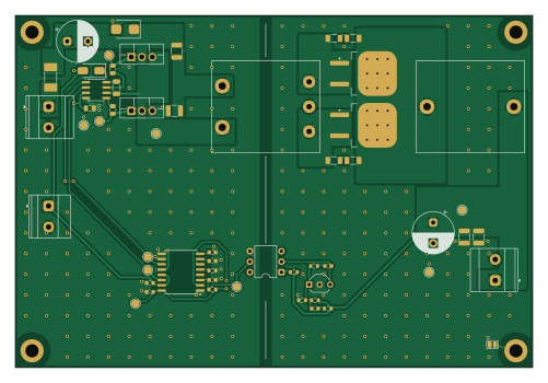
About the Isolated half bridge converter PCB
Isolated half bridge converter is an open source PCB design by E0FError, published on GitHub. It is a 2-layer board measuring 125 × 85 mm, with 44 components from 34 distinct parts.
Other key parts include the UCC27712D, UC3825ADWTR, 4N35 and TL431CLP. By type, the board carries 17 capacitors, 11 resistors, 4 ICs, 4 diodes, 3 connectors and 2 transistors.
From the project
Isolated 40-60 V to 12 V / 8 A half-bridge DC-DC converter: PLECS design, lab prototype, and a scripted two-layer PCB (Zener + KiCad)
An isolated half-bridge converter built to power a 96 W Peltier cooler. I worked on it across two DTU courses: 34652 Power Electronics I, where we chose the topology and did the design and simulation, and 34653 Power Electronics II Lab, where we built and tested the hardware. The PCB redesign in pcb/ came afterwards and grew out of the lab prototype.
- Compared flyback, forward, push-pull and half-bridge topologies by component stress factors, then picked the half-bridge with a centre-tapped secondary. - Derived the steady-state equations and the optimal turns ratio, and sized the output…
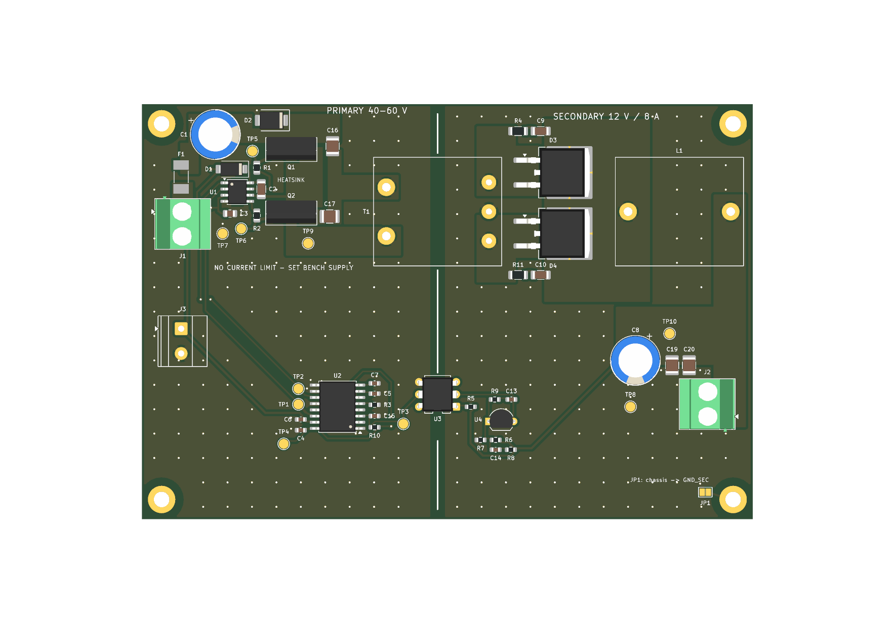
Main components on the Isolated half bridge converter
Isolated half bridge converter bill of materials (BOM)
44 components, 34 distinct parts.
| Qty | Part | Footprint | Refs |
|---|---|---|---|
| 1 | UCC27712D Texas Instruments | SOIC-8_3.9x4.9mm_P1.27mm | U1 |
| 1 | UC3825ADWTR Texas Instruments | SOIC-16W_7.5x10.3mm_P1.27mm | U2 |
| 1 | 4N35 Vishay | DIP-6_W7.62mm | U3 |
| 1 | TL431CLP Texas Instruments | TO-92_Inline_Wide | U4 |
| 2 | STF100N10F7 STMicroelectronics | TO-220F-3_Vertical | Q1, Q2 |
| 2 | 1711026 Phoenix Contact | TerminalBlock_Phoenix_MKDS-3-2-5.08_1x02_P5.08mm_Horizontal | J1, J2 |
| 1 | 1715721 Phoenix Contact | TerminalBlock_Phoenix_MKDS-1_5-2-5.08_1x02_P5.08mm_Horizontal | J3 |
| 1 | 0453004.MR 4A 125V Littelfuse | Fuse_Littelfuse-NANO2-451_453 | F1 |
| 1 | B65811J0000R087 RM8 N87 n=0.8 TDK | Transformer_RM8_HandWound | T1 |
| 1 | 1A 200V PN Rectifier | D_SMA | D1 |
| 1 | SMBJ70A 70V TVS Diode 600W Littelfuse | D_SMB | D2 |
| 2 | STPS20L60CG-TR STMicroelectronics | TO-263-2 | D3, D4 |
| 1 | B65811J0000R087 9.38uH TDK | Inductor_RM8_HandWound | L1 |
| 1 | UPW2A101MHD 100uF Nichicon | CP_Radial_D10.0mm_P5.00mm | C1 |
| 1 | 1uF 50V X7R | C_1206_3216Metric | C2 |
| 1 | 1uF 50V X7R | C_0805_2012Metric | C3 |
| 3 | 100nF 50V X7R | C_0603_1608Metric | C4, C6, C7 |
| 1 | 1nF 50V C0G | C_0603_1608Metric | C5 |
| 1 | EEU-FR1E471 470uF Panasonic | CP_Radial_D10.0mm_P5.00mm | C8 |
| 2 | 1nF 100V C0G | C_1206_3216Metric | C9, C10 |
Show 14 more
| Qty | Part | Footprint | Refs |
|---|---|---|---|
| 1 | 19.38nF 50V X7R | C_0603_1608Metric | C13 |
| 1 | 2.94nF 50V C0G | C_0603_1608Metric | C14 |
| 1 | 240pF 50V C0G | C_0603_1608Metric | C15 |
| 2 | 10uF 100V X7S | C_1210_3225Metric | C16, C17 |
| 2 | 10uF 25V X7R | C_1210_3225Metric | C19, C20 |
| 2 | 4.7 | R_0805_2012Metric | R1, R2 |
| 1 | 7.5k | R_0603_1608Metric | R3 |
| 2 | 10 | R_1206_3216Metric | R4, R11 |
| 1 | 3.38k | R_0603_1608Metric | R5 |
| 1 | 267k | R_0603_1608Metric | R6 |
| 1 | 70k | R_0603_1608Metric | R7 |
| 1 | 340 | R_0603_1608Metric | R8 |
| 1 | 5.76k | R_0603_1608Metric | R9 |
| 1 | 4.2k | R_0603_1608Metric | R10 |
Isolated half bridge converter design files
The KiCad project lives in the E0FError/isolated-half-bridge-converter repository on GitHub; these links point at the commit this page was built from.
Isolated half bridge converter: common questions
How big is the Isolated half bridge converter PCB?
The Isolated half bridge converter measures 125 × 85 mm, has 2 copper layers and is 1.62 mm thick.
How many components are on the Isolated half bridge converter?
44 components, from 34 distinct parts. The full bill of materials is listed on this page.
Where can I download the Isolated half bridge converter design files?
From the E0FError/isolated-half-bridge-converter repository on GitHub, which has the KiCad layout; the links under Design files point to each one.
Can I use the Isolated half bridge converter design in my own project?
The repository has no license, so all rights stay with E0FError. Use it as a reference, and ask the author before reusing the design.