
Strobe HMI

About the Strobe HMI PCB
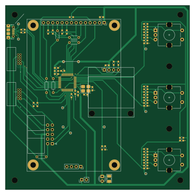
Strobe HMI is an open source STM32 PCB design by FLRHW, published on GitHub under the CERN-OHL-P-2.0 license. It is a 2-layer board measuring 100 × 100 mm, with 83 components from 29 distinct parts.
Its main chip is the STM32G431K8TX, from the STM32 family. By type, the board carries 28 resistors, 16 jumpers, 13 capacitors, 9 test points, 8 connectors and 3 switches.
It belongs with the audio and power & battery designs in this gallery.
From the project
While defining the project scope, I had to decide if I'd use the good old Xenon bulb or move to LEDs, as these have greatly evolved and are ubiquitous nowadays, making their way to commercial strobes (https://www.martin.com/en/products/atomic-3000-led). I have decided to stick to
While defining the project scope, I had to decide if I'd use the good old Xenon bulb or move to LEDs, as these have greatly evolved and are ubiquitous nowadays, making their way to commercial strobes (https://www.martin.com/en/products/atomic-3000-led). I have decided to stick to vintage tech, as in my mind this would perhaps bring more interesting power electronics challenges, since the bulb requires a somewhat high bus voltage and can draw very high peak currents when ionised.
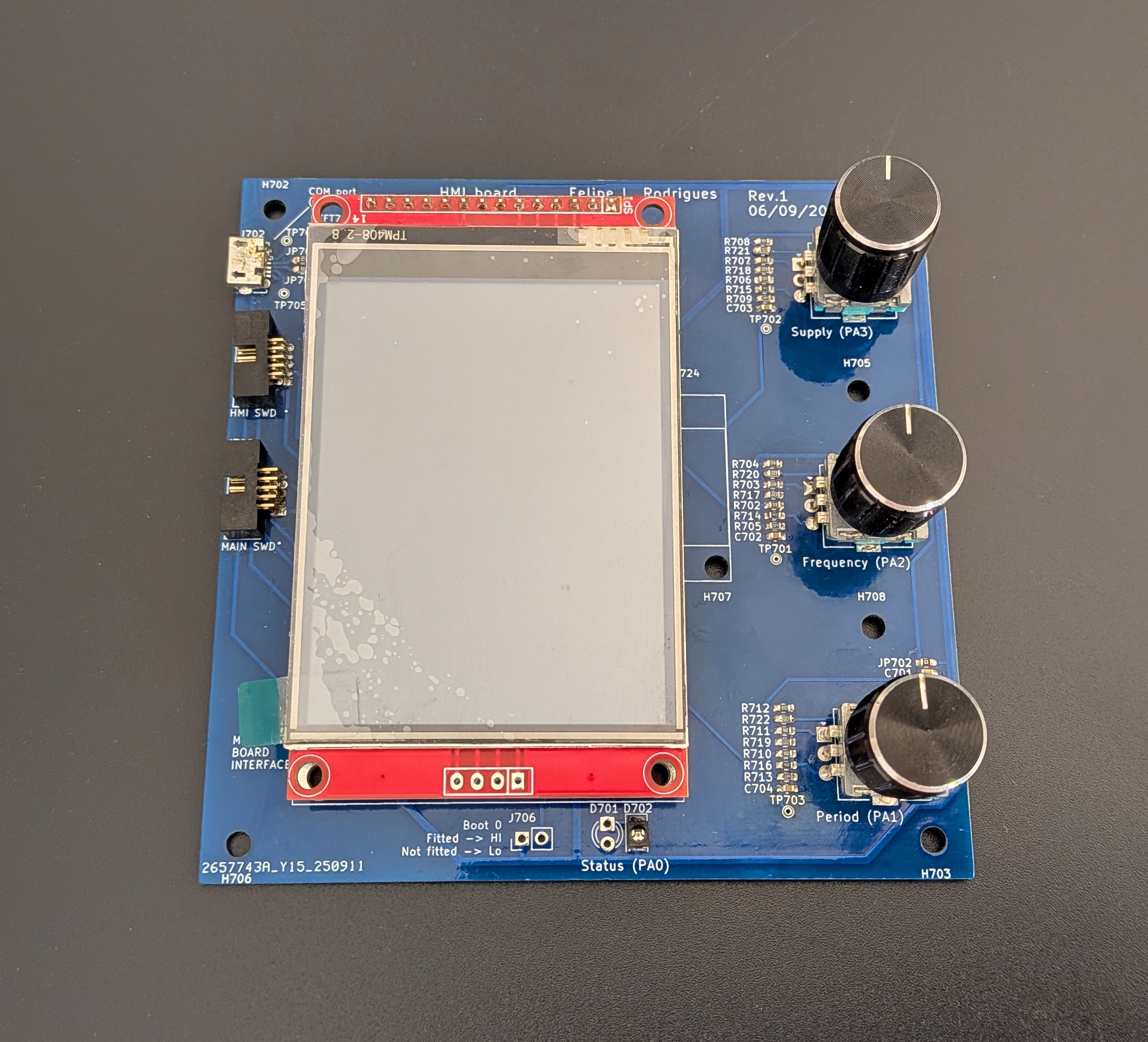
Main components on the Strobe HMI
Strobe HMI bill of materials (BOM)
83 components, 29 distinct parts — part numbers from the project's BOM.
| Qty | Part | Footprint | Refs |
|---|---|---|---|
| 1 | STM32G431K8TX STM32G431K8Tx | LQFP-32_7x7mm_P0.8mm | U701 |
| 1 | 20 MHz | Crystal_SMD_3225-4Pin_3.2x2.5mm_HandSoldering | Y701 |
| 1 | ZHOURI DC3 | IDC-Header_2x05_P2.54mm_Horizontal | J701 |
| 1 | 1050171001 Micro Type B | USB_Micro-B_Molex-105017-0001 | J702 |
| 2 | Conn_01x04_Pin | PinSocket_1x04_P2.54mm_Vertical | J703, J704 |
| 1 | Conn_01x14_Pin | PinSocket_1x14_P2.54mm_Vertical | J705 |
| 1 | Header | PinHeader_1x02_P2.54mm_Vertical | J706 |
| 2 | HX JN1.27-2x5 WZ H4.9 | JN1.27-2x5 WZ H4.9 | J707, J708 |
| 4 | Hand cut wire 0R Generic | R_Axial_DIN0204_L3.6mm_D1.6mm_P5.08mm_Horizontal | JP701, JP710, JP713, JP714 |
| 9 | RC0603JR-130RP 0R Yageo | R_0603_1608Metric_Pad0.98x0.95mm_HandSolder | JP702, JP704, JP705, JP706, JP707, JP709, JP711, JP712 +1 |
| 1 | Hand cut wire 8.12 Generic | Jumper_mm_L8.12_D1.2_H0.5 | JP703 |
| 2 | Hand cut wire 0R Generic | R_Axial_DIN0204_L3.6mm_D1.6mm_P7.62mm_Horizontal | JP708, JP715 |
| 3 | EncSw | RotaryEncoderSwitch_Oblong | SW701, SW702, SW703 |
| 1 | TFT_2.8IN_320X240 TFT_2.8in_320x240 | TFT_2.8_IN_320x240 | TFT701 |
| 9 | TestPoint | TestPoint_THTPad_D1.0mm_Drill0.5mm | TP701, TP702, TP703, TP704, TP705, TP706, TP707, TP708 +1 |
| 1 | OLED_128x64_SSD1306 | OLED_SSD1306_no_pins | OLED701 |
| 1 | Generic 3 mm LED LED Generic | LED_D3.0mm | D701 |
| 1 | LH T6MF-GGHH-1-E3L3 LED Osram | LED_PLCC-2_3x2mm_KA | D702 |
| 8 | 100N 100n | C_0603_1608Metric_Pad1.08x0.95mm_HandSolder | C701, C702, C703, C704, C705, C708, C709, C713 |
| 2 | 1u | C_0603_1608Metric_Pad1.08x0.95mm_HandSolder | C706, C707 |
Show 9 more
| Qty | Part | Footprint | Refs |
|---|---|---|---|
| 1 | 100n | C_0603_1608Metric_Pad1.08x0.95mm_HandSolder | C710 |
| 2 | 22P 22p | C_0603_1608Metric_Pad1.08x0.95mm_HandSolder | C711, C712 |
| 4 | 10K 10k | R_0603_1608Metric_Pad0.98x0.95mm_HandSolder | R701, R725, R727, R728 |
| 10 | 1k | R_0603_1608Metric_Pad0.98x0.95mm_HandSolder | R702, R703, R704, R706, R707, R708, R710, R711 +2 |
| 3 | 220K 220k | R_0603_1608Metric_Pad0.98x0.95mm_HandSolder | R705, R709, R713 |
| 3 | 44K 44k | R_0603_1608Metric_Pad0.98x0.95mm_HandSolder | R714, R715, R716 |
| 3 | 22K 22k | R_0603_1608Metric_Pad0.98x0.95mm_HandSolder | R717, R718, R719 |
| 3 | 11K 11k | R_0603_1608Metric_Pad0.98x0.95mm_HandSolder | R720, R721, R722 |
| 2 | 4K7 4k7 | R_0603_1608Metric_Pad0.98x0.95mm_HandSolder | R723, R724 |
Strobe HMI design files
The KiCad project lives in the FLRHW/Strobe_HMI repository on GitHub; these links point at the commit this page was built from.
Strobe HMI: common questions
What microcontroller does the Strobe HMI use?
The Strobe HMI is built around the STM32G431K8TX, from the STM32 family.
How big is the Strobe HMI PCB?
The Strobe HMI measures 100 × 100 mm, has 2 copper layers and is 1.66 mm thick.
How many components are on the Strobe HMI?
83 components, from 29 distinct parts, with part numbers taken from the project's own BOM. The full bill of materials is listed on this page.
Where can I download the Strobe HMI design files?
From the FLRHW/Strobe_HMI repository on GitHub, which has the KiCad layout, the schematic and the BOM; the links under Design files point to each one.
Can I use the Strobe HMI design in my own project?
Yes, under the terms of its CERN-OHL-P-2.0 license, which FLRHW chose for the repository.
Can I test firmware for the Strobe HMI without the hardware?
Yes. HardLabs builds a simulation of the board from its netlist and BOM, so you can run and debug STM32 firmware against it before you order a PCB.
Similar boards
 STM32
LumenPnP Motherboard
opulo-inc
149 × 95 mm296 parts4LCC-BY-SA-4.03.7k STM32
Type g
google
169 × 30 mm24 parts2LApache-2.02.9k STM32
Base
52.3 × 52.3 mm36 parts2LApache-2.02.9k STM32
Main panel
234 × 84 mm26 parts4LApache-2.02.9k STM32
Type a
150 × 30 mm14 parts2LApache-2.02.9k STM32
Type c
188 × 30 mm17 parts2LApache-2.02.9k