
Receiver


About the Receiver PCB
Receiver is an open source PCB design by fmckeogh, published on GitHub under the MPL-2.0 license. It is a 2-layer board measuring 19.1 × 12.7 mm, with 5 components from 2 distinct parts.
It belongs with the iot & wireless designs in this gallery.
From the project
BLE-based light electric vehicle control system
nRF52810 microcontrollers SSD1306 display NCR18650GA battery Hall-effect thumb control
[ ] MVP (move thumb and motor spins as a result) [ ] Proper BLE connection [ ] Display telemetry [ ] Transparent passthrough to VESC for configuration from PC/phone [ ] CLI for configuring remote/receiver [ ] OTA firmware updates of remote and receiver [ ] Battery percent on phone [ ] HomeKit integration
Receiver bill of materials (BOM)
5 components, 2 distinct parts.
| Qty | Part | Footprint | Refs |
|---|---|---|---|
| 4 | TEST-POINT3 | PAD.03X.05 | GND1, SWDCLK1, SWDIO1, VCC1 |
| 1 | 0.1UF-0402-16V-10% | 0402_mod | C1 |
Receiver design files
The KiCad project lives in the fmckeogh/bluefly repository on GitHub; these links point at the commit this page was built from.
Receiver: common questions
How big is the Receiver PCB?
The Receiver measures 19.1 × 12.7 mm, has 2 copper layers and is 1.6002 mm thick.
How many components are on the Receiver?
5 components, from 2 distinct parts. The full bill of materials is listed on this page.
Where can I download the Receiver design files?
From the fmckeogh/bluefly repository on GitHub, which has the KiCad layout; the links under Design files point to each one.
Can I use the Receiver design in my own project?
Yes, under the terms of its MPL-2.0 license, which fmckeogh chose for the repository.
More boards in bluefly
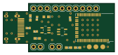
Similar boards
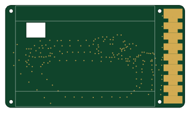
EinkPDA screen
TalismanDesign
95 × 54 mm27 parts2LApache-2.02.0k
RPi RM0 WiFi/Bluetooth Module
schlae
11.1 × 14 mm76 parts6LNo license1.0k
L0 USB
Luos-io
20.3 × 15.3 mm19 parts2LMIT547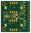
Breakout board
26.7 × 27.9 mm29 parts2LMIT547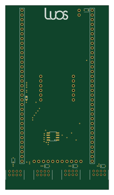
Stm32f0 disco Luos shield
55.9 × 99.1 mm26 parts2LMIT547
L0 USBA
20.3 × 15.3 mm19 parts2LMIT547