
Pd adapter

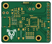
About the Pd adapter PCB
Pd adapter is an open source STM32 PCB design by fullyautomated, published on GitHub. It is a 4-layer board measuring 45 × 38 mm, with 54 components from 34 distinct parts.
Its main chip is the C80488, from the STM32 family. Other key parts include the C132291 and C191884. By type, the board carries 15 capacitors, 15 resistors, 12 diodes, 5 connectors, 3 ICs and 2 switches.
It belongs with the power & battery and iot & wireless designs in this gallery.
From the project
Fully Automated line of USB-C PD PPS boards
USB-C Programmable Power Supply Source and Sink.
Back side optimized for JLCSMT, front for hand placing.
Ecosystem Idea: - Stackable Ferrets; you can have any\* amount of type C ports you can possibly need. Ferrets can have individual legacy electricity I/O, or can be tied to a single common bus. With the - Configuration Board (top position only) you can monitor power flow and change port settings (source/sink, current and voltage) - this has a management interface (USB UART) and maybe Bluetooth/Wifi with an ESP32. Energy is stored in the - Battery Board; 4s BMS which can be attached to the…
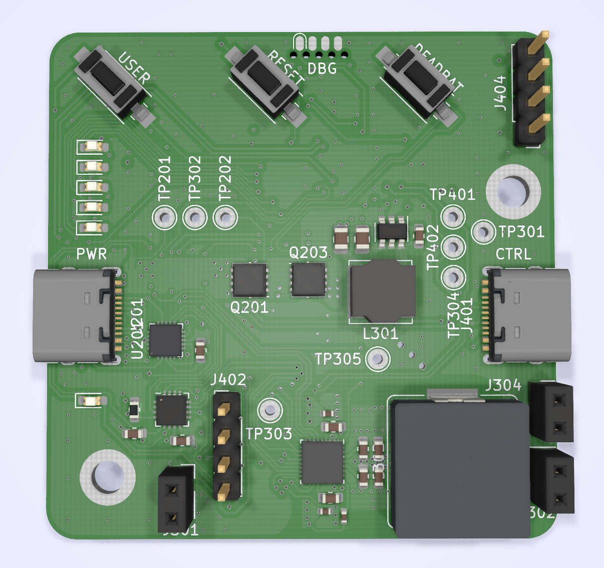
Main components on the Pd adapter
Pd adapter bill of materials (BOM)
54 components, 34 distinct parts — part numbers from the project's BOM.
| Qty | Part | Footprint | Refs |
|---|---|---|---|
| 1 | C132291 FUSB302BMPX | WQFN-14-1EP_2.5x2.5mm_P0.5mm_EP1.45x1.45mm | U1 |
| 1 | C191884 TPS54202DDC | SOT-23-6 | U2 |
| 1 | C80488 STM32F072C8Tx | LQFP-48_7x7mm_P0.5mm | U3 |
| 1 | USB | USB_C_Receptacle_XKB_U262-16XN-4BVC11 | J1 |
| 1 | DBG | SOIC_clipProgSmall | J2 |
| 1 | EXT | PinHeader_1x06_P2.54mm_Vertical | J3 |
| 1 | Qwiic | JST_SH_SM04B-SRSS-TB_1x04-1MP_P1.00mm_Horizontal | J4 |
| 1 | EXT | PinHeader_1x04_P2.54mm_Vertical | J5 |
| 1 | Transistor | transistor_10x10mm | H5 |
| 1 | RST | SW_SPST_PTS636_G | SW1 |
| 1 | USER | SW_SPST_PTS636_G | SW2 |
| 4 | C266462 5V | D_SOD-523 | D1, D2, D6, D7 |
| 2 | C136161 3.3V | D_SOD-523 | D3, D4 |
| 1 | C22619 24V | D_SOD-323 | D5 |
| 1 | C2286 Red/2V | LED_0603_1608Metric_Castellated | D8 |
| 1 | C72041 Blue/2.8V | LED_0603_1608Metric_Castellated | D9 |
| 1 | C72043 Green/3.3V | LED_0603_1608Metric_Castellated | D10 |
| 1 | C2290 White/2.9V | LED_0603_1608Metric_Castellated | D11 |
| 1 | C72038 Yellow/2.9V | LED_0603_1608Metric_Castellated | D12 |
| 1 | C86069 10uH | L_1210_3225Metric | L1 |
Show 14 more
| Qty | Part | Footprint | Refs |
|---|---|---|---|
| 7 | C14663 100nF/50V | C_0603_1608Metric | C1, C5, C10, C11, C12, C13, C14 |
| 1 | C13585 10uF | C_1206_3216Metric | C2 |
| 2 | C14663 100nF | C_0603_1608Metric | C3, C9 |
| 3 | C19702 10uF/10V | C_0603_1608Metric | C4, C7, C15 |
| 1 | C19702 10uF | C_0603_1608Metric | C6 |
| 1 | C39148 56pF/50V | C_0603_1608Metric | C8 |
| 6 | C23162 4.7k | R_0603_1608Metric | R1, R2, R3, R7, R9, R10 |
| 1 | C23185 49.9 | R_0603_1608Metric | R4 |
| 1 | C25803 100k | R_0603_1608Metric | R5 |
| 1 | C31850 22k | R_0603_1608Metric | R6 |
| 1 | C25804 10k | R_0603_1608Metric | R8 |
| 2 | C23185 130 | R_0603_1608Metric | R11, R15 |
| 2 | C23182 47 | R_0603_1608Metric | R12, R14 |
| 1 | C22859 0 | R_0603_1608Metric | R13 |
Pd adapter design files
The KiCad project lives in the fullyautomated/ferret repository on GitHub; these links point at the commit this page was built from.
Pd adapter: common questions
What microcontroller does the Pd adapter use?
The Pd adapter is built around the C80488, from the STM32 family.
How big is the Pd adapter PCB?
The Pd adapter measures 45 × 38 mm, has 4 copper layers and is 1.6 mm thick.
How many components are on the Pd adapter?
54 components, from 34 distinct parts, with part numbers taken from the project's own BOM. The full bill of materials is listed on this page.
Where can I download the Pd adapter design files?
From the fullyautomated/ferret repository on GitHub, which has the KiCad layout and the BOM; the links under Design files point to each one.
Can I use the Pd adapter design in my own project?
The repository has no license, so all rights stay with fullyautomated. Use it as a reference, and ask the author before reusing the design.
Can I test firmware for the Pd adapter without the hardware?
Yes. HardLabs builds a simulation of the board from its netlist and BOM, so you can run and debug STM32 firmware against it before you order a PCB.
More boards in ferret
Similar boards
 STM32
STM32AxxSolder
AxxAxx
39 × 82.5 mm122 parts2LGPL-3.01.7k STM32
STM32AIOC
skuep
21 × 31.5 mm47 parts2LMIT1.4k STM32
STM32Ferris
pierrechevalier83
208.8 × 86.8 mm102 parts2LSHL-2.11.3k STM32
STM32Module 16S
stuartpittaway
71.1 × 89.6 mm113 parts4LCC-BY-NC-4.01.1k STM32
STM32Djinn
tzarc
192.3 × 150.5 mm216 parts2LCERN-OHL-S-2.0988 STM32
STM32Ghoul
228.6 × 79.4 mm163 parts2LCERN-OHL-S-2.0988