
Motor pid

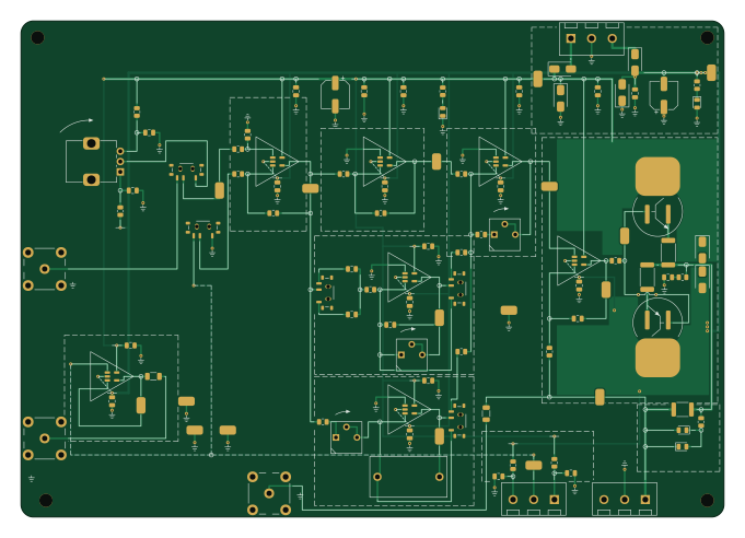
About the Motor pid PCB
Motor pid is an open source PCB design by gallicchio, published on GitHub under the CERN-OHL-P-2.0 license. It is a 2-layer board measuring 170 × 120 mm, with 106 components from 48 distinct parts.
Other key parts include the LM321MFX/NOPB. By type, the board carries 28 capacitors, 26 resistors, 17 test points, 7 ICs, 6 connectors and 6 diodes.
From the project
The motor-position feedback loop of Learning the Art of Electronics (Hayes & Horowitz), Lab 10L, as a 170 x 120 mm printed circuit board whose silkscreen is the schematic. A motorized slide fader (the lab's Bourns PSM01-082A-103B2, or any 100 mm fader with a 10k track and a 6–11
The motor-position feedback loop of Learning the Art of Electronics (Hayes & Horowitz), Lab 10L, as a 170 x 120 mm printed circuit board whose silkscreen is the schematic. A motorized slide fader (the lab's Bourns PSM01-082A-103B2, or any 100 mm fader with a 10k track and a 6–11 V motor) wires to two screw terminals; the board holds the fader's wiper at the position a knob or a signal generator asks for, with proportional, derivative and integral terms the student switches in and turns up one at a time, exactly as the lab does.
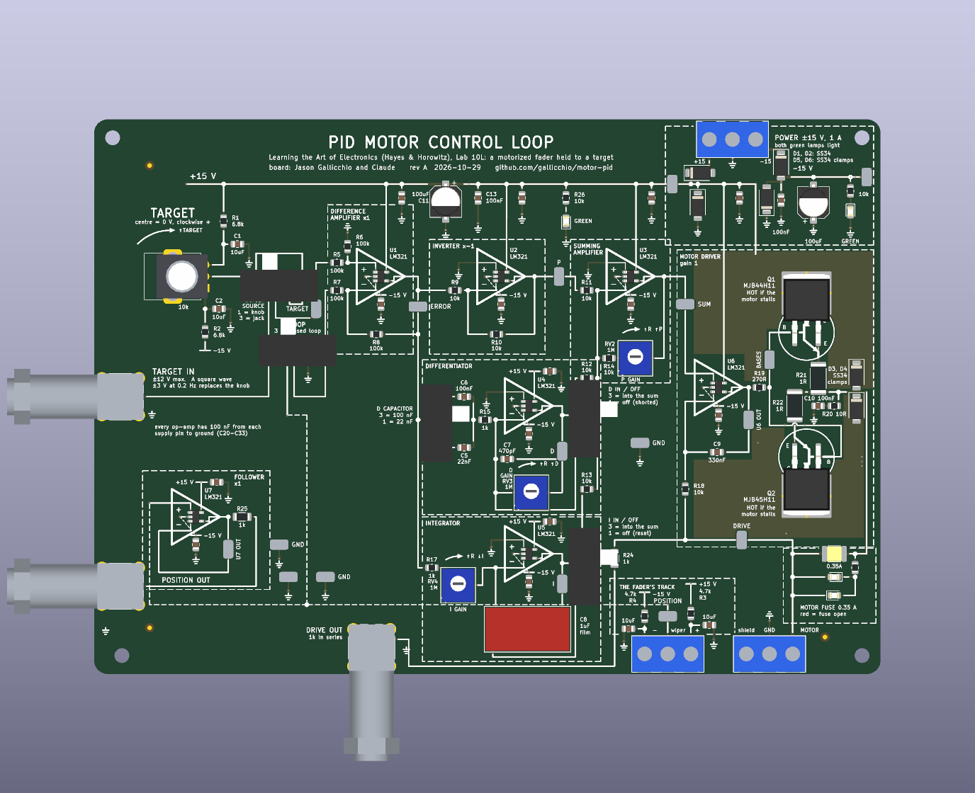
Main components on the Motor pid
Motor pid bill of materials (BOM)
106 components, 48 distinct parts — part numbers from the project's BOM.
| Qty | Part | Footprint | Refs |
|---|---|---|---|
| 7 | LM321MFX/NOPB LM321 | SOT-23-5 | U1, U2, U3, U4, U5, U6, U7 |
| 1 | MJB44H11T4G MJB44H11 | TO-263-2 | Q1 |
| 1 | MJB45H11T4G MJB45H11 | TO-263-2 | Q2 |
| 3 | BNC-KYWE-295-W4-N BNC | BNC_KYWE_RightAngle | J1, J2, J3 |
| 1 | KF301-5.0-3P MOTOR + - shield | TerminalBlock_KF301_1x03_P5.00mm | J4 |
| 1 | KF301-5.0-3P POT 1 (+) 2 (wiper) 3 (-) | TerminalBlock_KF301_1x03_P5.00mm | J5 |
| 1 | KF301-5.0-3P +15 / GND / -15 | TerminalBlock_KF301_1x03_P5.00mm | J6 |
| 1 | 1812L035/60GR 0.35A | Fuse_1812_4532Metric | F1 |
| 1 | RK09K1130A70 10k | Potentiometer_Alps_RK09K_Single_Vertical | RV1 |
| 3 | 3362P-1-105 1M | Potentiometer_Bourns_3362P_Vertical | RV2, RV3, RV4 |
| 1 | MSK12C02 TARGET SOURCE | SW_SPDT_Shouhan_MSK12C02 | SW1 |
| 1 | MSK12C02 LOOP | SW_SPDT_Shouhan_MSK12C02 | SW2 |
| 1 | MSK12C02 D IN / OFF | SW_SPDT_Shouhan_MSK12C02 | SW3 |
| 1 | MSK12C02 I IN / OFF | SW_SPDT_Shouhan_MSK12C02 | SW4 |
| 1 | MSK12C02 D CAPACITOR | SW_SPDT_Shouhan_MSK12C02 | SW5 |
| 1 | RH-5019 TARGET | TestPoint_Loop_RH-5019 | TP1 |
| 1 | RH-5019 ERROR | TestPoint_Loop_RH-5019 | TP2 |
| 1 | RH-5019 P | TestPoint_Loop_RH-5019 | TP3 |
| 1 | RH-5019 D | TestPoint_Loop_RH-5019 | TP4 |
| 1 | RH-5019 I | TestPoint_Loop_RH-5019 | TP5 |
Show 28 more
| Qty | Part | Footprint | Refs |
|---|---|---|---|
| 1 | RH-5019 SUM | TestPoint_Loop_RH-5019 | TP6 |
| 1 | RH-5019 DRIVE | TestPoint_Loop_RH-5019 | TP7 |
| 1 | RH-5019 POSITION | TestPoint_Loop_RH-5019 | TP8 |
| 1 | RH-5019 +15V | TestPoint_Loop_RH-5019 | TP9 |
| 1 | RH-5019 -15V | TestPoint_Loop_RH-5019 | TP10 |
| 1 | RH-5019 BASES | TestPoint_Loop_RH-5019 | TP11 |
| 1 | RH-5019 U6 OUT | TestPoint_Loop_RH-5019 | TP12 |
| 1 | RH-5019 U7 OUT | TestPoint_Loop_RH-5019 | TP13 |
| 4 | RH-5019 GND | TestPoint_Loop_RH-5019 | TP100, TP101, TP102, TP103 |
| 2 | KT-0805G GREEN | LED_0805_2012Metric | LED1, LED2 |
| 2 | NCD0805R1 RED | LED_0805_2012Metric | LED3, LED4 |
| 6 | SS34 | D_SMA | D1, D2, D3, D4, D5, D6 |
| 4 | CL21A106KAYNNNE 10uF | C_0805_2012Metric | C1, C2, C3, C4 |
| 1 | CL21B223KBANNNC 22nF | C_0805_2012Metric | C5 |
| 18 | CC0805KRX7R9BB104 100nF | C_0805_2012Metric | C6, C10, C13, C14, C20, C21, C22, C23 +10 |
| 1 | 0805B471K500NT 470pF | C_0805_2012Metric | C7 |
| 1 | ECWF2W105JA 1uF | C_Film_Panasonic_ECWF_L18.1mm_W9.3mm_P15.00mm | C8 |
| 1 | 0805B334K500NT 330nF | C_0805_2012Metric | C9 |
| 2 | JVJ25V100M6x5 100uF | CP_Elec_6.3x5.4 | C11, C12 |
| 2 | 0805W8F6801T5E 6.8k | R_0805_2012Metric | R1, R2 |
| 2 | 0805W8F4701T5E 4.7k | R_0805_2012Metric | R3, R4 |
| 4 | 0805W8F1003T5E 100k | R_0805_2012Metric | R5, R6, R7, R8 |
| 9 | 0805W8F1002T5E 10k | R_0805_2012Metric | R9, R10, R11, R12, R13, R14, R18, R26 +1 |
| 3 | 0805W8F1001T5E 1k | R_0805_2012Metric | R15, R17, R23 |
| 1 | 0805W8F2700T5E 270R | R_0805_2012Metric | R19 |
| 1 | 0805W8F100JT5E 10R | R_0805_2012Metric | R20 |
| 2 | FRC2512J1R0TS 1R | R_2512_6332Metric | R21, R22 |
| 2 | 1206W4F1001T5E 1k | R_1206_3216Metric | R24, R25 |
Motor pid design files
The KiCad project lives in the gallicchio/motor-pid repository on GitHub; these links point at the commit this page was built from.
Motor pid: common questions
How big is the Motor pid PCB?
The Motor pid measures 170 × 120 mm, has 2 copper layers and is 1.6 mm thick.
How many components are on the Motor pid?
106 components, from 48 distinct parts, with part numbers taken from the project's own BOM. The full bill of materials is listed on this page.
Where can I download the Motor pid design files?
From the gallicchio/motor-pid repository on GitHub, which has the KiCad layout, the schematic and the BOM; the links under Design files point to each one.
Can I use the Motor pid design in my own project?
Yes, under the terms of its CERN-OHL-P-2.0 license, which gallicchio chose for the repository.