
MIO-Blind-Bot

About the MIO-Blind-Bot PCB
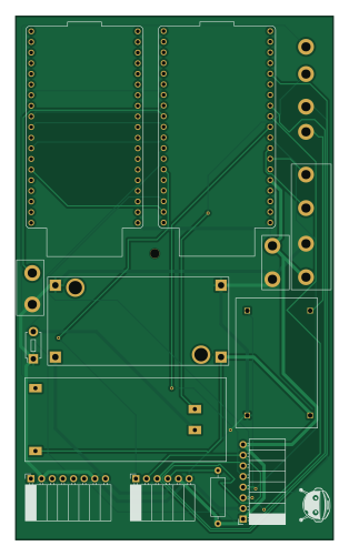
MIO-Blind-Bot is an open source PCB design by GuruManoharGuptaBaratam, published on GitHub. It is a 2-layer board measuring 75.7 × 125 mm, with 6 components from 6 distinct parts.
Other key parts include the LM2596 (3.3v).
It belongs with the power & battery, wearables and sensors designs in this gallery.
From the project
Hardware design (KiCad) for MIO-Blind_BOT — the power and interconnect board for MIO, a wearable dual-ESP32 assistive system for blind users. Integrates battery management, buck regulation, pan-tilt servo control, IMU, and TFT status display, with Bluetooth audio feedback via earbuds
Custom hardware design for MIO — a wearable assistive device for blind and low-vision users
This repository contains the complete PCB hardware design for MIO, a dual-ESP32 wearable assistive device. The board serves as the central interconnect and power-management platform of the system, tying together the compute modules, motion sensing, camera pan-tilt actuation, display feedback, and battery power delivery into a single wearable-ready design.

Main components on the MIO-Blind-Bot
MIO-Blind-Bot bill of materials (BOM)
6 components, 6 distinct parts — part numbers from the project's BOM.
| Qty | Part | Footprint | Refs |
|---|---|---|---|
| 1 | LM2596 (3.3v) | CONV_USA_MC00100 | U12 |
| 1 | (10kohm) | R_Axial_DIN0309_L9.0mm_D3.2mm_P12.70mm_Horizontal | 10kohmR |
| 1 | BMS 1S-NC | BMS-2S 20A | BMS 2S 20A |
| 1 | CA-1235 (5V) | Converter_MP1495_Module | CA-1235 (5V) |
| 1 | MPU6050 None | PinSocket_1x08_P2.54mm_Horizontal | MPU6050-IMU |
| 1 | TFT SPI (1.8) | PinSocket_1x08_P2.54mm_Horizontal | TFT-SPI (1.8) |
MIO-Blind-Bot design files
The KiCad project lives in the GuruManoharGuptaBaratam/MIO-Blind-Bot-PCB repository on GitHub; these links point at the commit this page was built from.
MIO-Blind-Bot: common questions
How big is the MIO-Blind-Bot PCB?
The MIO-Blind-Bot measures 75.7 × 125 mm, has 2 copper layers and is 1.6 mm thick.
How many components are on the MIO-Blind-Bot?
6 components, from 6 distinct parts, with part numbers taken from the project's own BOM. The full bill of materials is listed on this page.
Where can I download the MIO-Blind-Bot design files?
From the GuruManoharGuptaBaratam/MIO-Blind-Bot-PCB repository on GitHub, which has the KiCad layout, the schematic and the BOM; the links under Design files point to each one.
Can I use the MIO-Blind-Bot design in my own project?
The repository has no license, so all rights stay with GuruManoharGuptaBaratam. Use it as a reference, and ask the author before reusing the design.
Similar boards
View base
scottbez1
81.2 × 81.2 mm81 parts2LApache-2.022.2k
View screen
35 × 35 mm12 parts2LApache-2.022.2k
BM28B0.6-24DSBreakout
15.2 × 35.6 mm3 parts2LApache-2.022.2k
LevelShifterBreakout
15.2 × 20.3 mm5 parts2LApache-2.022.2k
ChainlinkDriverTester
198.1 × 95.3 mm123 parts2LApache-2.04.2k
ChainlinkBase
98.4 × 190.5 mm119 parts2LApache-2.04.2k