
Pcb lowpower timer

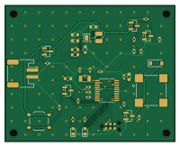
About the Pcb lowpower timer
Pcb lowpower timer is an open source STM32 PCB design by haiha-ux, published on GitHub. It is a 2-layer board measuring 50 × 40 mm, with 43 components from 30 distinct parts.
Its main chip is the STM32L031F6P6, from the STM32 family. Other key parts include the TPS61099DRVR. By type, the board carries 16 resistors, 11 capacitors, 4 transistors, 4 diodes, 2 ICs and 2 connectors.
It belongs with the power & battery designs in this gallery.
From the project
2xAA low-power timer board in KiCad 10: soft-latch power button, 0.5 uA off current, TPS61099 boost, STM32L031 with 32 kHz RTC, JLCPCB fab files
A 50 × 40 mm timer board that runs from two AA cells. One button turns it on; the firmware keeps itself powered through a HOLD pin and turns itself off on a long press. When it is off, the battery sees only leakage, about 0.5 µA typical. The board has a 32.768 kHz RTC, a magnetic buzzer, two LEDs and a switched battery-voltage divider. It is a 2-layer board, and every part has an LCSC number for JLCPCB assembly.
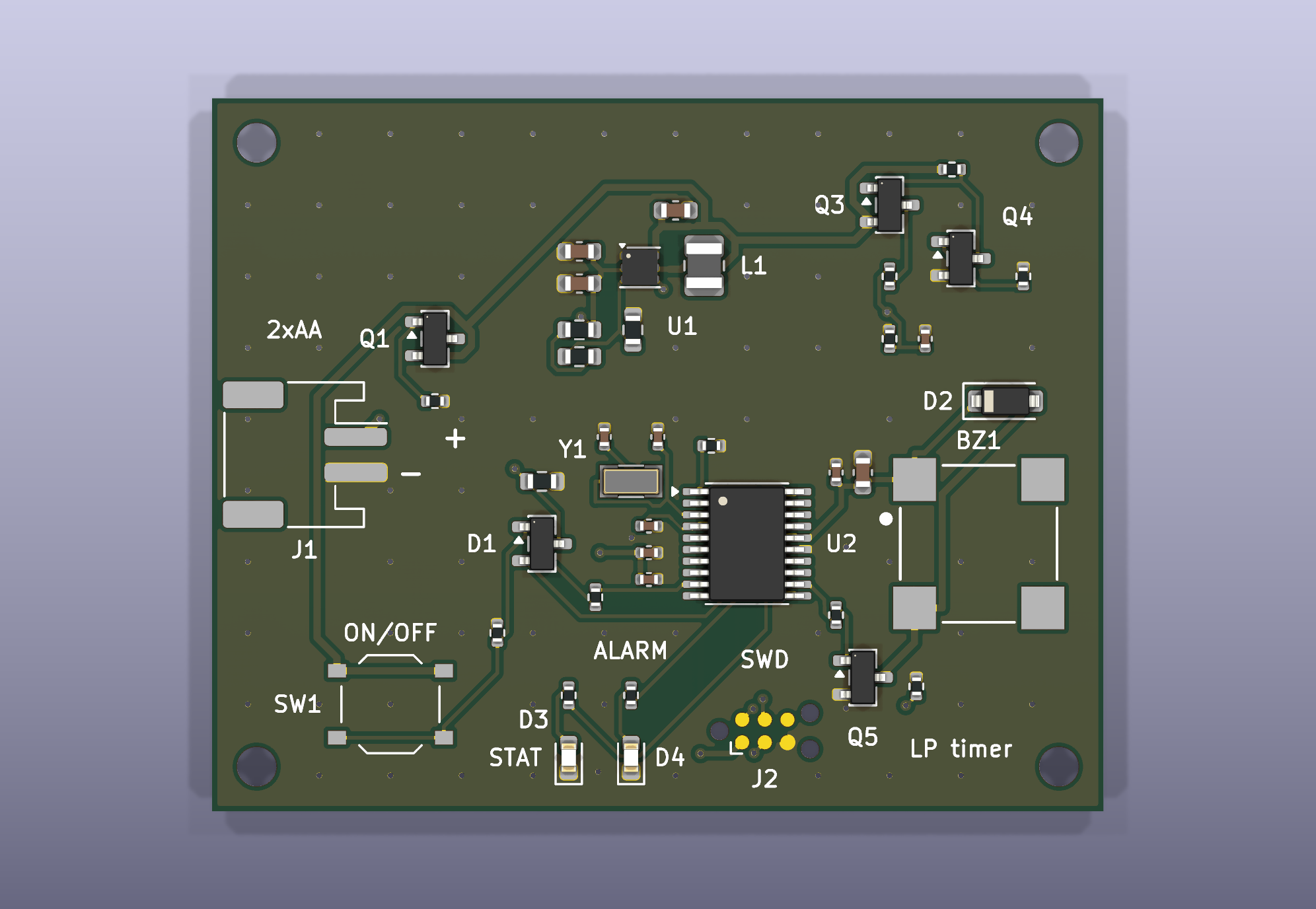
Main components on the Pcb lowpower timer
Pcb lowpower timer bill of materials (BOM)
43 components, 30 distinct parts — part numbers from the project's BOM.
| Qty | Part | Footprint | Refs |
|---|---|---|---|
| 1 | TPS61099DRVR TPS61099DRV | WSON-6-1EP_2x2mm_P0.65mm_EP1x1.6mm | U1 |
| 1 | STM32L031F6P6 | TSSOP-20_4.4x6.5mm_P0.65mm | U2 |
| 1 | DMG2305UX-7 DMG2305UX | SOT-23 | Q1 |
| 1 | AO3401A | SOT-23 | Q3 |
| 1 | 2N7002 | SOT-23 | Q4 |
| 1 | MMBT3904(RANGE:100-300) MMBT3904 | SOT-23 | Q5 |
| 1 | Q13FC13500002 32.768kHz 7pF | Crystal_SMD_3215-2Pin_3.2x1.5mm | Y1 |
| 1 | S2B-PH-SM4-TB(LF)(SN) 2xAA | JST_PH_S2B-PH-SM4-TB_1x02-1MP_P2.00mm_Horizontal | J1 |
| 1 | SWD TC2030-NL | Tag-Connect_TC2030-IDC-NL_2x03_P1.27mm_Vertical | J2 |
| 1 | MLT-8530 | Buzzer_Huaneng_MLT-8530 | BZ1 |
| 1 | TS-1187A-B-A-B ON/OFF | SW_Push_1P1T_XKB_TS-1187A | SW1 |
| 1 | BAT54C | SOT-23 | D1 |
| 1 | 1N4148W | D_SOD-123 | D2 |
| 1 | KT-0603R RED STAT | LED_0603_1608Metric | D3 |
| 1 | KT-0603R RED ALARM | LED_0603_1608Metric | D4 |
| 1 | 74404024022 2.2uH | L_1008_2520Metric | L1 |
| 3 | CL10A106KP8NNNC 10uF | C_0603_1608Metric | C1, C2, C3 |
| 3 | CL05B104KO5NNNC 100nF | C_0402_1005Metric | C4, C8, C11 |
| 1 | CL10A475KO8NNNC 4.7uF | C_0603_1608Metric | C5 |
| 1 | CL05B103KB5NNNC 10nF | C_0402_1005Metric | C6 |
Show 10 more
| Qty | Part | Footprint | Refs |
|---|---|---|---|
| 1 | CL05A105KA5NQNC 1uF | C_0402_1005Metric | C7 |
| 2 | 0402CG6R8C500NT 6.8pF | C_0402_1005Metric | C9, C10 |
| 5 | 0402WGF1003TCE 100k | R_0402_1005Metric | R1, R7, R11, R12, R14 |
| 2 | 0603WAF2004T5E 2M | R_0603_1608Metric | R2, R6 |
| 1 | 0603WAF3003T5E 300k | R_0603_1608Metric | R3 |
| 1 | 0603WAF1004T5E 1M | R_0603_1608Metric | R4 |
| 3 | 0402WGF1004TCE 1M | R_0402_1005Metric | R5, R9, R10 |
| 1 | 0402WGF1002TCE 10k | R_0402_1005Metric | R8 |
| 1 | 0402WGF4700TCE 470 | R_0402_1005Metric | R13 |
| 2 | 0402WGF1001TCE 1k | R_0402_1005Metric | R15, R16 |
Pcb lowpower timer design files
The KiCad project lives in the haiha-ux/pcb-lowpower-timer repository on GitHub; these links point at the commit this page was built from.
- Layoutlowpower_timer.kicad_pcb
- Schematiclowpower_timer.kicad_sch
- BOMfab/BOM_JLCPCB.csv
Pcb lowpower timer: common questions
What microcontroller does the Pcb lowpower timer use?
The Pcb lowpower timer is built around the STM32L031F6P6, from the STM32 family.
How big is the Pcb lowpower timer?
The Pcb lowpower timer measures 50 × 40 mm, has 2 copper layers and is 1.6 mm thick.
How many components are on the Pcb lowpower timer?
43 components, from 30 distinct parts, with part numbers taken from the project's own BOM. The full bill of materials is listed on this page.
Where can I download the Pcb lowpower timer design files?
From the haiha-ux/pcb-lowpower-timer repository on GitHub, which has the KiCad layout, the schematic and the BOM; the links under Design files point to each one.
Can I use the Pcb lowpower timer design in my own project?
The repository has no license, so all rights stay with haiha-ux. Use it as a reference, and ask the author before reusing the design.
Can I test firmware for the Pcb lowpower timer without the hardware?
Yes. HardLabs builds a simulation of the board from its netlist and BOM, so you can run and debug STM32 firmware against it before you order a PCB.
Similar boards
 STM32
LumenPnP Motherboard
opulo-inc
149 × 95 mm296 parts4LCC-BY-SA-4.03.7k STM32
Type g
google
169 × 30 mm24 parts2LApache-2.02.9k STM32
Base
52.3 × 52.3 mm36 parts2LApache-2.02.9k STM32
Main panel
234 × 84 mm26 parts4LApache-2.02.9k STM32
Type a
150 × 30 mm14 parts2LApache-2.02.9k STM32
Type c
188 × 30 mm17 parts2LApache-2.02.9k