MosfetSwitch

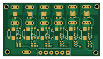
About the MosfetSwitch PCB
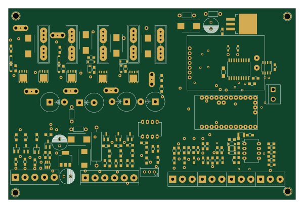
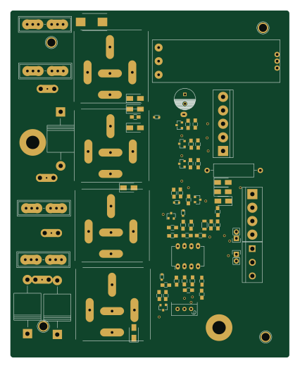
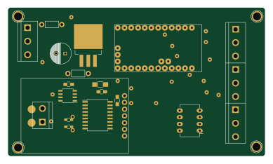
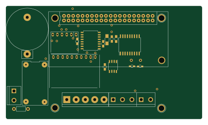
MosfetSwitch is an open source PCB design by ieb, published on GitHub. It is a 2-layer board measuring 90 × 50 mm, with 78 components from 33 distinct parts.
By type, the board carries 24 diodes, 24 resistors, 18 connectors and 12 transistors.
From the project
Replacement engine electronics for a Volvo Penta D2-40 and other MDI based engines.
In July 2021 my boat was hit by lightning. The Volvo Penta D2-40 MDI unit that manages the Engine, a Volvo Penta D2-40F failed badly leaving the starter motor engaged and nearly causing an engine fire.
Update 20240417: In service, no issues after 3 years.
(see pcb/EngineManagementSimpleWithRelays.sch )
This project is based on the standard wiring for the core engine which is a Perkins 100. In that form the engine is controlled by switches, relays and a few flyback diodes. The only part of the original engine control that survived the strike was the Volvo Penta buttons, so those are used by…
MosfetSwitch bill of materials (BOM)
78 components, 33 distinct parts — part numbers from the project's BOM.
| Qty | Part | Footprint | Refs |
|---|---|---|---|
| 1 | 2N2907 SI7137 | Si7137PowerPak | Q1 |
| 6 | BC817-40 | SOT-23 | Q2, Q4, Q6, Q8, Q10, Q12 |
| 5 | SI7137 | Si7137PowerPak | Q3, Q5, Q7, Q9, Q11 |
| 1 | ToSwitches | bornier6 | P1 |
| 1 | CONN_1 0v | CrimpBlade | P2 |
| 1 | CONN_1 CH3In | CrimpBlade | P3 |
| 1 | CONN_1 CH2In | CrimpBlade | P4 |
| 1 | CH1In | CrimpBlade | P5 |
| 1 | J1939 Ch3Out | CrimpBlade | P6 |
| 1 | Ch2Out | CrimpBlade | P7 |
| 1 | Ch1Out | CrimpBlade | P8 |
| 1 | CH6In | CrimpBlade | P9 |
| 1 | CH5In | CrimpBlade | P10 |
| 1 | CH4In | CrimpBlade | P11 |
| 1 | Ch6Out | CrimpBlade | P12 |
| 1 | Ch5Out | CrimpBlade | P13 |
| 1 | Ch4Out | CrimpBlade | P14 |
| 4 | hole | 1pin | P15, P16, P17, P18 |
| 5 | SMBJ30CA-TR TSV | DO-214AB_Handsoldering | D1, D2, D16, D17, D18 |
| 1 | 1N5819 SMBJ30CA-TR TSV | DO-214AB_Handsoldering | D3 |
Show 13 more
| Qty | Part | Footprint | Refs |
|---|---|---|---|
| 3 | 1N5819 ZENER | D_SOD-123 | D4, D5, D6 |
| 6 | 1N4001 | D_SOD-123 | D7, D8, D9, D22, D23, D24 |
| 6 | 1N4001 | Resistor_Horizontal_RM7mm | D13, D14, D15, D28, D29, D30 |
| 3 | ZENER | D_SOD-123 | D19, D20, D21 |
| 1 | 2.2K 10K | R_0805_HandSoldering | R1 |
| 8 | 10K | R_0805_HandSoldering | R2, R5, R6, R7, R8, R13, R14, R19 |
| 2 | 47K 10K | R_0805_HandSoldering | R3, R4 |
| 1 | 10R 10K | R_0805_HandSoldering | R9 |
| 3 | 10K 470R | R_0805_HandSoldering | R10, R11, R12 |
| 5 | 10K | R_0805_HandSoldering | R15, R16, R17, R18, R20 |
| 1 | 100K 10K | R_0805_HandSoldering | R21 |
| 1 | 100K 470R | R_0805_HandSoldering | R22 |
| 2 | 470R | R_0805_HandSoldering | R23, R24 |
MosfetSwitch design files
The KiCad project lives in the ieb/EngineManagement repository on GitHub; these links point at the commit this page was built from.
MosfetSwitch: common questions
How big is the MosfetSwitch PCB?
The MosfetSwitch measures 90 × 50 mm, has 2 copper layers and is 1.6 mm thick.
How many components are on the MosfetSwitch?
78 components, from 33 distinct parts, with part numbers taken from the project's own BOM. The full bill of materials is listed on this page.
Where can I download the MosfetSwitch design files?
From the ieb/EngineManagement repository on GitHub, which has the KiCad layout and the BOM; the links under Design files point to each one.
Can I use the MosfetSwitch design in my own project?
The repository has no license, so all rights stay with ieb. Use it as a reference, and ask the author before reusing the design.