
GrblHAL-Sender

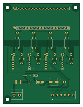
About the GrblHAL-Sender PCB
GrblHAL-Sender is an open source PCB design by Jay-Tech, published on GitHub. It is a 2-layer board measuring 70 × 92 mm, with 47 components from 16 distinct parts.
Other key parts include the LTV-817S-TA1-B. By type, the board carries 21 resistors, 5 transistors, 5 diodes, 4 ICs, 4 connectors and 4 LEDs.
From the project
Four-channel opto-isolated high-side switch board. 70 × 92 mm against v1's 150 × 115 — 64% less area, same circuit per channel.
Four-channel opto-isolated high-side switch board. 70 × 92 mm against v1's 150 × 115 — 64% less area, same circuit per channel.
Generated and placed, not routed. DRC is clean on the placement; the routing is the work left to do, exactly as v1 was at this stage.
Unchanged: the entire channel circuit. Same optocoupler, same AO3401A, same 8.2 V gate clamp, same resistor values. That is the point — v1's bench-test procedure validates this board too, and the one part of the design nobody has watched work does not get disturbed by a packaging exercise.
Main components on the GrblHAL-Sender
GrblHAL-Sender bill of materials (BOM)
47 components, 16 distinct parts — part numbers from the project's BOM.
| Qty | Part | Footprint | Refs |
|---|---|---|---|
| 4 | LTV-817S-TA1-B Lite-On | SOP-4_7.5x4.1mm_P2.54mm | U1, U2, U3, U4 |
| 5 | AO3401A Alpha & Omega | SOT-23 | Q1, Q2, Q3, Q4, Q9 |
| 1 | 1729128 Phoenix Contact | TerminalBlock_Phoenix_MKDS-1,5-2-5.08_1x02_P5.08mm_Horizontal | J1 |
| 1 | 1727052 Phoenix Contact | TerminalBlock_Phoenix_MKDS-1-6-3.81_1x06_P3.81mm_Horizontal | J2 |
| 2 | PPTC201LFBN-RC Sullins | PinSocket_1x20_P2.54mm_Vertical | J4, J5 |
| 1 | MF-MSMF110/24X-2 1.1A Bourns | Fuse_1812_4532Metric | F1 |
| 1 | SMAJ30A Littelfuse | D_SMA | TVS1 |
| 4 | LTST-C170KGKT GRN Lite-On | LED_0805_2012Metric | LED1, LED2, LED3, LED4 |
| 5 | MMSZ5237B-7-F Diodes Inc | D_SOD-123 | D1, D2, D3, D4, D9 |
| 1 | EEE-FK1H470XP 47UF/50V Panasonic | CP_Elec_6.3x7.7 | C1 |
| 1 | CL21B104KBCNNNC 100nF Samsung | C_0805_2012Metric | C2 |
| 5 | RC0805FR-07100KL 100k Yageo | R_0805_2012Metric | R6, R101, R201, R301, R401 |
| 4 | RC0805FR-074K7L 4k7 Yageo | R_0805_2012Metric | R102, R202, R302, R402 |
| 4 | RC0805FR-0710KL 10k Yageo | R_0805_2012Metric | R103, R203, R303, R403 |
| 4 | RC0805FR-072K2L 2k2 Yageo | R_0805_2012Metric | R104, R204, R304, R404 |
| 4 | RC0805FR-07470RL 470R Yageo | R_0805_2012Metric | R105, R205, R305, R405 |
GrblHAL-Sender design files
The KiCad project lives in the Jay-Tech/GrblHAL-Sender repository on GitHub; these links point at the commit this page was built from.
GrblHAL-Sender: common questions
How big is the GrblHAL-Sender PCB?
The GrblHAL-Sender measures 70 × 92 mm, has 2 copper layers and is 1.6 mm thick.
How many components are on the GrblHAL-Sender?
47 components, from 16 distinct parts, with part numbers taken from the project's own BOM. The full bill of materials is listed on this page.
Where can I download the GrblHAL-Sender design files?
From the Jay-Tech/GrblHAL-Sender repository on GitHub, which has the KiCad layout, the schematic and the BOM; the links under Design files point to each one.
Can I use the GrblHAL-Sender design in my own project?
The repository has no license, so all rights stay with Jay-Tech. Use it as a reference, and ask the author before reusing the design.
Earlier revisions in the repo: shop-output-board