
Modulator

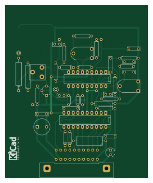
About the Modulator PCB
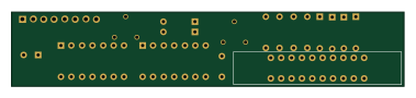
Modulator is an open source PCB design by Lazarus-L-o-n-g, published on GitHub under the CC-BY-NC-4.0 license. It is a 2-layer board measuring 78 × 94 mm, with 43 components from 41 distinct parts.
By type, the board carries 16 capacitors, 14 resistors, 3 diodes, 2 connectors, 1 crystal and 1 relay.
It belongs with the keyboards designs in this gallery.
From the project
All schematics and PCBs are made using KiCad.
All schematics and PCBs are made using KiCad.
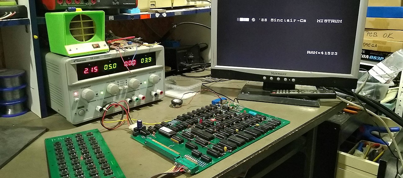
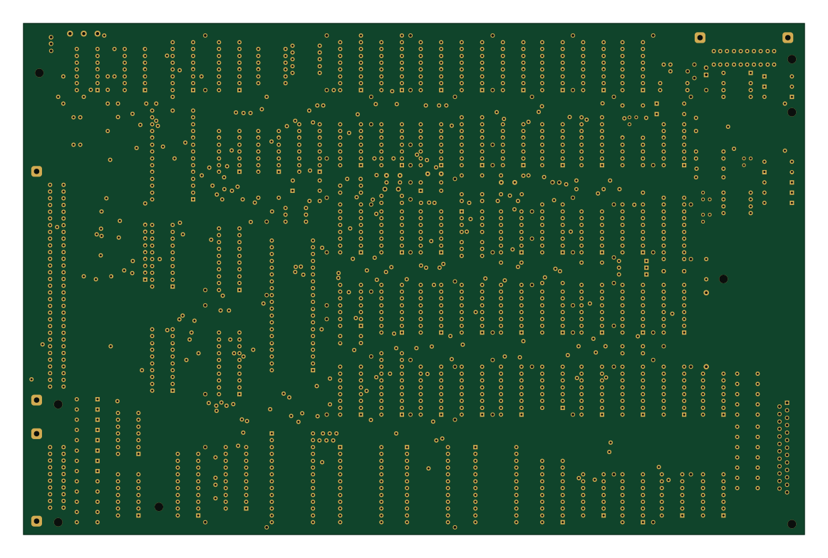
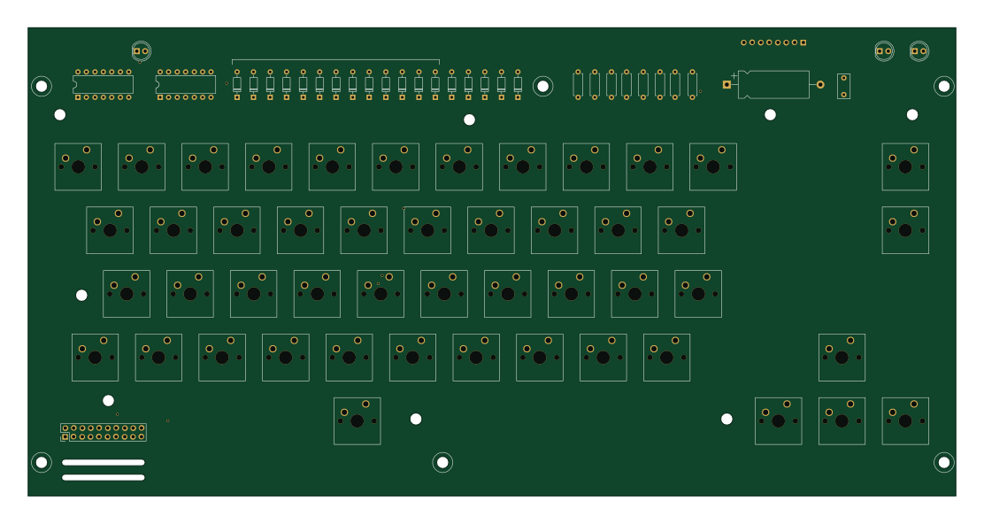
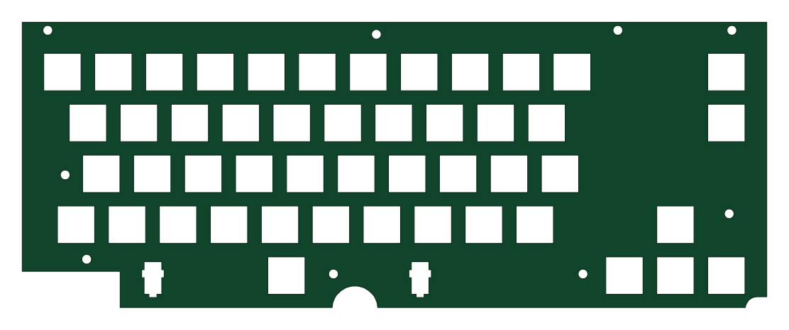
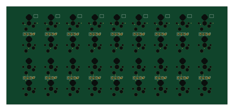
The newly designed extended Cherry MX Keyboard features: - Mechanical Cherry MX switches - ZX Spectrum compatibility - Optional bus or external power supply (external is deafult for Mistrum) - Extended to separate cursors keys, delete key and special Mistrum keys (key Mistrum, NMI and RESET), realized as logic switches - Two LED indicators, optional (for example BOOT, DRIVE) - Two PCBs - main board and mask - Identical size and mounting holes as PMD-85 coputer keyboard
Modulator bill of materials (BOM)
43 components, 41 distinct parts — part numbers from the project's BOM.
| Qty | Part | Footprint | Refs |
|---|---|---|---|
| 1 | 14MHZ 4,43MHz | C2 | X1 |
| 1 | CONN_1 | Pin_D0.7mm_L6.5mm_W1.8mm_FlatFork | P1 |
| 1 | CONN_1 | 1pin | P2 |
| 1 | LM1886 | DIP-20__300_ELL | IO1 |
| 1 | LM1889 | DIP-18__300_ELL | IO2 |
| 1 | TX5176211 CONN_20 | TY5112011 | K1 |
| 1 | SWITCH_INV | PIN_ARRAY_3X1 | PR1 |
| 1 | KFY46 KC509 | TO-92_Wide | T1 |
| 1 | 470R | CA6V | TR1 |
| 3 | KA206 | D3 | D1, D2, D3 |
| 1 | INDUCTOR | R4 | L1 |
| 1 | 47UF/6.3V 50uF | C2V8 | C1 |
| 1 | 47UF/6.3V 100n | C2 | C2 |
| 1 | 2N2 100n | C3 | C3 |
| 1 | 150P 100p | CP4 | C4 |
| 1 | 270P 100p | CP5 | C5 |
| 1 | 27P 60p | WN70419 | C6 |
| 1 | 47UF/6.3V 36p | C1 | C7 |
| 1 | 150N 36p | C2 | C8 |
| 1 | 27P 10n | C3 | C9 |
Show 21 more
| Qty | Part | Footprint | Refs |
|---|---|---|---|
| 1 | 220N 47uF | C1V5 | C10 |
| 1 | 100N 100n | C2 | C11 |
| 1 | 470UF 60p | WN70419 | C12 |
| 1 | 27P 10uF | C1 | C13 |
| 1 | 27P 10n | C2 | C14 |
| 1 | 1n | C1 | C15 |
| 1 | 680P 47uF | CP7 | C16 |
| 1 | 10K 4k7 | R7 | R1 |
| 1 | 10K 5k6 | R2 | R2 |
| 1 | 100R 2k2 | R2 | R3 |
| 1 | 680R 100k | R4 | R4 |
| 1 | 4k7 | R4 | R5 |
| 1 | 1k | R3 | R6 |
| 1 | 5K6 1k | R4 | R7 |
| 1 | 4K7 3k3 | R4 | R8 |
| 1 | 4K7 1k8 | R4 | R9 |
| 1 | 4K7 820R | R4 | R10 |
| 1 | 4K7 270R | R4 | R11 |
| 1 | 4K7 270R | R3 | R12 |
| 1 | 220R 82R | R2 | R13 |
| 1 | 33R 2R2 | R6 | R14 |
Modulator design files
The KiCad project lives in the Lazarus-L-o-n-g/Mistrum repository on GitHub; these links point at the commit this page was built from.
Modulator: common questions
How big is the Modulator PCB?
The Modulator measures 78 × 94 mm, has 2 copper layers and is 1.6002 mm thick.
How many components are on the Modulator?
43 components, from 41 distinct parts, with part numbers taken from the project's own BOM. The full bill of materials is listed on this page.
Where can I download the Modulator design files?
From the Lazarus-L-o-n-g/Mistrum repository on GitHub, which has the KiCad layout, the schematic and the BOM; the links under Design files point to each one.
Can I use the Modulator design in my own project?
It is published under CC-BY-NC-4.0, which limits how it may be reused; read the license before building on it.
 byrantech


 google