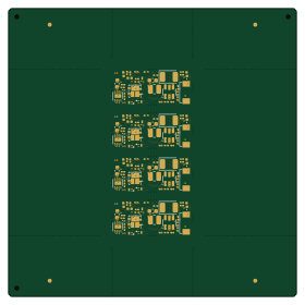
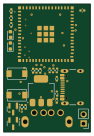
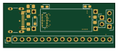
E24-receiver board


About the E24-receiver board
E24-receiver board is an open source PCB design by mikesmitty, published on GitHub. It is a 2-layer board measuring 24 × 8.6 mm, with 21 components from 21 distinct parts.
E24-receiver board bill of materials (BOM)
21 components, 21 distinct parts — part numbers from the project's BOM.
| Qty | Part | Footprint | Refs |
|---|---|---|---|
| 1 | 505070-2422 | 5050702422 | J1 |
| 1 | TRACK_LEFT | SolderWirePad_1x01_SMD_1x2mm | J2 |
| 1 | C9739 MOTOR- | SolderWirePad_1x01_SMD_1x2mm | J3 |
| 1 | LAMP_FRONT | SolderWirePad_1x01_SMD_1x2mm | J4 |
| 1 | CAP+ | SolderWirePad_1x01_SMD_1x2mm | J5 |
| 1 | AUX1 | SolderWirePad_1x01_SMD_1x2mm | J6 |
| 1 | AUX3 | SolderWirePad_1x01_SMD_1x2mm | J7 |
| 1 | AUX10 | SolderWirePad_1x01_SMD_1x2mm | J8 |
| 1 | AUX12 | SolderWirePad_1x01_SMD_1x2mm | J9 |
| 1 | SPEAKER- | SolderWirePad_1x01_SMD_1x2mm | J10 |
| 1 | GND1 | SolderWirePad_1x01_SMD_1x2mm | J11 |
| 1 | TRACK_RIGHT | SolderWirePad_1x01_SMD_1x2mm | J12 |
| 1 | MOTOR+ | SolderWirePad_1x01_SMD_1x2mm | J13 |
| 1 | U+ | SolderWirePad_1x01_SMD_1x2mm | J14 |
| 1 | VCC | SolderWirePad_1x01_SMD_1x2mm | J15 |
| 1 | LAMP_REAR | SolderWirePad_1x01_SMD_1x2mm | J16 |
| 1 | AUX2 | SolderWirePad_1x01_SMD_1x2mm | J17 |
| 1 | AUX4 | SolderWirePad_1x01_SMD_1x2mm | J18 |
| 1 | AUX11 | SolderWirePad_1x01_SMD_1x2mm | J19 |
| 1 | SPEAKER+ | SolderWirePad_1x01_SMD_1x2mm | J20 |
Show 1 more
| Qty | Part | Footprint | Refs |
|---|---|---|---|
| 1 | GND2 | SolderWirePad_1x01_SMD_1x2mm | J21 |
E24-receiver board design files
The KiCad project lives in the mikesmitty/electronics-projects repository on GitHub; these links point at the commit this page was built from.
E24-receiver board: common questions
How big is the E24-receiver board?
The E24-receiver board measures 24 × 8.6 mm, has 2 copper layers and is 1.6 mm thick.
How many components are on the E24-receiver board?
21 components, from 21 distinct parts, with part numbers taken from the project's own BOM. The full bill of materials is listed on this page.
Where can I download the E24-receiver board design files?
From the mikesmitty/electronics-projects repository on GitHub, which has the KiCad layout, the schematic and the BOM; the links under Design files point to each one.
Can I use the E24-receiver board design in my own project?
The repository has no license, so all rights stay with mikesmitty. Use it as a reference, and ask the author before reusing the design.