Logic Circuit

About the Logic Circuit PCB
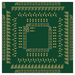
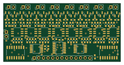
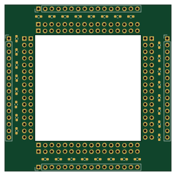
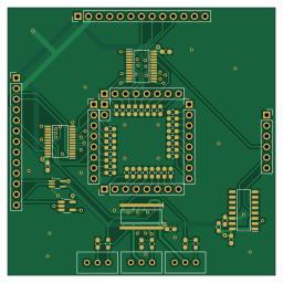
Logic Circuit is an open source PCB design by omzz15, published on GitHub. It is a 4-layer board measuring 64 × 64 mm, with 61 components from 15 distinct parts.
Other key parts include the 74HC4514PW,118, 74AHC123AD,118, MC74VHC1G32DFT1G-L22038 and SN74LVC1G08DBVR-EV. By type, the board carries 36 resistors, 8 capacitors, 6 ICs and 4 crystals.
From the project
256 Byte Magnetic Memory Project
*Note: Any time I say MAD, I am refering to the memory address.
Magnetic-core memory was an early form of non-volatile random access memory (RAM) used in early computing, notably the Apollo Guidance Computers. I am working with a friend to create our own magnetic core memory to interface with an 8-bit computer. This repository contains the code, schematics, and PCBs we make. Currently, we have made the schematic and PCB for the logic component of the memory as well as code to emulate the rest of the memory and interface with computers through serial. This is still a work in progress and has…
Main components on the Logic Circuit
Logic Circuit bill of materials (BOM)
61 components, 15 distinct parts.
| Qty | Part | Footprint | Refs |
|---|---|---|---|
| 2 | 74HC4514PW,118 | SOP65P640X110-24N | IC1, IC3 |
| 2 | 74AHC123AD,118 | SOIC127P600X175-16N | IC4, IC5 |
| 1 | MC74VHC1G32DFT1G-L22038 | SOT-353_SC-70-5_Handsoldering | U1 |
| 1 | SN74LVC1G08DBVR-EV | SOT-23-5_HandSoldering | U2 |
| 4 | Conn_01x08 | PinHeader_1x08_P2.54mm_Vertical | X1, X2, Y1, Y2 |
| 1 | Conn_01x02 | PinSocket_1x02_P2.54mm_Vertical | D_DAT1 |
| 2 | Conn_01x13 | PinHeader_1x13_P2.54mm_Vertical | IN1, IS_OUT1 |
| 1 | Conn_01x06 | PinSocket_1x06_P2.54mm_Vertical | PULSE_DBG1 |
| 3 | R_Potentiometer | Potentiometer_Bourns_3296W_Vertical | RV1, RV2, RV3 |
| 2 | 1000p | C_0603_1608Metric_Pad1.08x0.95mm_HandSolder | C1, C2 |
| 2 | 220p | C_0603_1608Metric_Pad1.08x0.95mm_HandSolder | C3, C4 |
| 4 | 1u | C_0603_1608Metric_Pad1.08x0.95mm_HandSolder | C6, C7, C8, C9 |
| 32 | 10k | R_0603_1608Metric_Pad0.98x0.95mm_HandSolder | R1, R2, R3, R4, R6, R8, R11, R14 +24 |
| 2 | 1k | R_0603_1608Metric_Pad0.98x0.95mm_HandSolder | R39, R44 |
| 2 | 5.1k | R_0603_1608Metric_Pad0.98x0.95mm_HandSolder | R42, R43 |
Logic Circuit design files
The KiCad project lives in the omzz15/Magnetic-Memory repository on GitHub; these links point at the commit this page was built from.
Logic Circuit: common questions
How big is the Logic Circuit PCB?
The Logic Circuit measures 64 × 64 mm, has 4 copper layers and is 1.6 mm thick.
How many components are on the Logic Circuit?
61 components, from 15 distinct parts. The full bill of materials is listed on this page.
Where can I download the Logic Circuit design files?
From the omzz15/Magnetic-Memory repository on GitHub, which has the KiCad layout and the schematic; the links under Design files point to each one.
Can I use the Logic Circuit design in my own project?
The repository has no license, so all rights stay with omzz15. Use it as a reference, and ask the author before reusing the design.