
OM-16LED

About the OM-16LED PCB
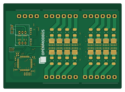
OM-16LED is an open source STM32 PCB design by OpenModbus, published on GitHub under the GPL-3.0 license. It is a 2-layer board measuring 100 × 72 mm, with 98 components from 25 distinct parts.
Its main chip is the STM32G474RET6, from the STM32 family. Other key parts include the 2EDN7534BXTSA1, R-78E12-1.0/X9, R-78E3.3-0.5 and THVD1450DRBR. By type, the board carries 23 capacitors, 19 resistors, 17 fuses, 16 transistors, 12 ICs and 6 connectors.
It belongs with the iot & wireless designs in this gallery.
From the project
A compact industrial-grade 16-channel Modbus RTU LED driver.
A compact industrial-grade 16-channel Modbus RTU LED driver module featuring high-current MOSFET outputs, per-bank terminal grouping, wide load voltage range, DIN-rail support, and full configuration via Modbus holding registers. Designed for lighting automation, distributed I/O, and custom control applications.
The Open Modbus OM-16LED is a 16-channel low-side LED driver module intended for industrial automation, lighting control, and distributed I/O networks using Modbus RTU over RS-485. It switches DC LED loads such as LED strips, architectural lighting, and indicator arrays up to 60 VDC…
Main components on the OM-16LED
OM-16LED bill of materials (BOM)
98 components, 25 distinct parts — part numbers from the project's BOM.
| Qty | Part | Footprint | Refs |
|---|---|---|---|
| 1 | STM32G474RET6 STM32G474RETx STMicroelectronics | LQFP-64_10x10mm_P0.5mm | U1 |
| 8 | 2EDN7534BXTSA1 2EDN7534B Infineon Technologies | SOT-23-6 | U2, U3, U4, U5, U6, U7, U8, U9 |
| 1 | R-78E12-1.0/X9 R-78E12-1.0 RECOM | Converter_DCDC_RECOM_R-78E-0.5_THT | U10 |
| 1 | R-78E3.3-0.5 RECOM | Converter_DCDC_RECOM_R-78E-0.5_THT | U11 |
| 1 | THVD1450DRBR THVD1450DR Texas Instruments | VSON-8-1EP_3x3mm_P0.65mm_EP1.6x2.4mm | U12 |
| 16 | NTMFS4D0N08XT1G NTMFS4D0N08X onsemi | ONSemi_SO-8FL_488AA | Q1, Q2, Q3, Q4, Q5, Q6, Q7, Q8 +8 |
| 1 | 10030002303 2EDGVC-5.0-04P DEGSON | TerminalBlock_DEGSON_2EDGVC-5.0-04P_No_SilkScreen | J1 |
| 4 | 10030002306 2EDGVC-5.0-06P DEGSON | TerminalBlock_DEGSON_2EDGVC-5.0-06P_No_SilkScreen | J2, J3, J4, J5 |
| 1 | 02x03 1.27 | PinHeader_2x03_P1.27mm_Vertical | J6 |
| 16 | 0679H8000-05 8A 60VDC Bel Fuse | Fuse_0679H | F1, F2, F3, F4, F5, F6, F7, F8 +8 |
| 1 | 0466001.NR 1A Littelfuse | Fuse_1206_3216Metric | F17 |
| 1 | CD123D-B140LR Bourns | D_SOD-123 | D1 |
| 1 | SMAJ28A Littelfuse | D_SMA | D2 |
| 1 | SM712-02HTG SM712_SOT23 Littelfuse | SOT-23 | D3 |
| 2 | LTST-C190EKT RED LITEON | LED_0603_1608Metric | D4, D5 |
| 8 | GRT21BR71H104KE01L 0.1uF Murata | C_0805_2012Metric | C1, C2, C3, C4, C5, C6, C7, C8 |
| 4 | GRT31CR61H106KE01L 10uF Murata | C_1206_3216Metric | C9, C10, C11, C12 |
| 1 | GRM188R61E475KE11D 4.7uF Murata | C_0603_1608Metric | C13 |
| 7 | GCJ188R71H104KA12D 0.1uF Murata | C_0603_1608Metric | C14, C15, C16, C17, C19, C22, C23 |
| 2 | GRT188R61H105KE13D 1uF Murata | C_0603_1608Metric | C18, C21 |
Show 5 more
| Qty | Part | Footprint | Refs |
|---|---|---|---|
| 1 | GCM188R71H103KA37D 10nF Murata | C_0603_1608Metric | C20 |
| 16 | ERJ-H3EF10R0V 10 Panasonic | R_0603_1608Metric | R1, R2, R3, R4, R5, R6, R7, R8 +8 |
| 1 | ERJ-H3EF1002V 10K Panasonic | R_0603_1608Metric | R17 |
| 1 | ERJ-UP3J222V 2K2 Panasonic | R_0603_1608Metric | R18 |
| 1 | ERJ-UP3J471V 470 Panasonic | R_0603_1608Metric | R19 |
OM-16LED design files
The KiCad project lives in the OpenModbus/OM-16LED repository on GitHub; these links point at the commit this page was built from.
- Layoutkicad/OM-16LED.kicad_pcb
- Schematickicad/OM-16LED.kicad_sch
- BOMassets/bom.csv
OM-16LED: common questions
What microcontroller does the OM-16LED use?
The OM-16LED is built around the STM32G474RET6, from the STM32 family.
How big is the OM-16LED PCB?
The OM-16LED measures 100 × 72 mm, has 2 copper layers and is 1.6 mm thick.
How many components are on the OM-16LED?
98 components, from 25 distinct parts, with part numbers taken from the project's own BOM. The full bill of materials is listed on this page.
Where can I download the OM-16LED design files?
From the OpenModbus/OM-16LED repository on GitHub, which has the KiCad layout, the schematic and the BOM; the links under Design files point to each one.
Can I use the OM-16LED design in my own project?
Yes, under the terms of its GPL-3.0 license, which OpenModbus chose for the repository.
Can I test firmware for the OM-16LED without the hardware?
Yes. HardLabs builds a simulation of the board from its netlist and BOM, so you can run and debug STM32 firmware against it before you order a PCB.
Similar boards
 STM32
STM32AxxSolder
AxxAxx
39 × 82.5 mm122 parts2LGPL-3.01.7k STM32
STM32AIOC
skuep
21 × 31.5 mm47 parts2LMIT1.4k STM32
STM32Ferris
pierrechevalier83
208.8 × 86.8 mm102 parts2LSHL-2.11.3k STM32
STM32Module 16S
stuartpittaway
71.1 × 89.6 mm113 parts4LCC-BY-NC-4.01.1k STM32
STM32Djinn
tzarc
192.3 × 150.5 mm216 parts2LCERN-OHL-S-2.0988 STM32
STM32Ghoul
228.6 × 79.4 mm163 parts2LCERN-OHL-S-2.0988