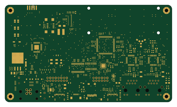
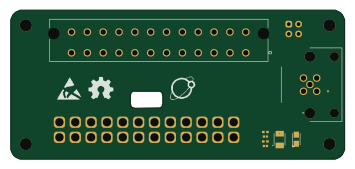
Sd adapter

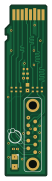
About the Sd adapter PCB
Sd adapter is an open source PCB design by oro-os, published on GitHub under the MIT license. It is a 2-layer board measuring 11 × 45.1 mm, with 13 components from 6 distinct parts.
By type, the board carries 6 resistors, 4 capacitors, 2 LEDs and 1 inductor.
From the project
The Oro OS CI/CD pipeline including PCBs, CAD files, firmware and server infrastructure
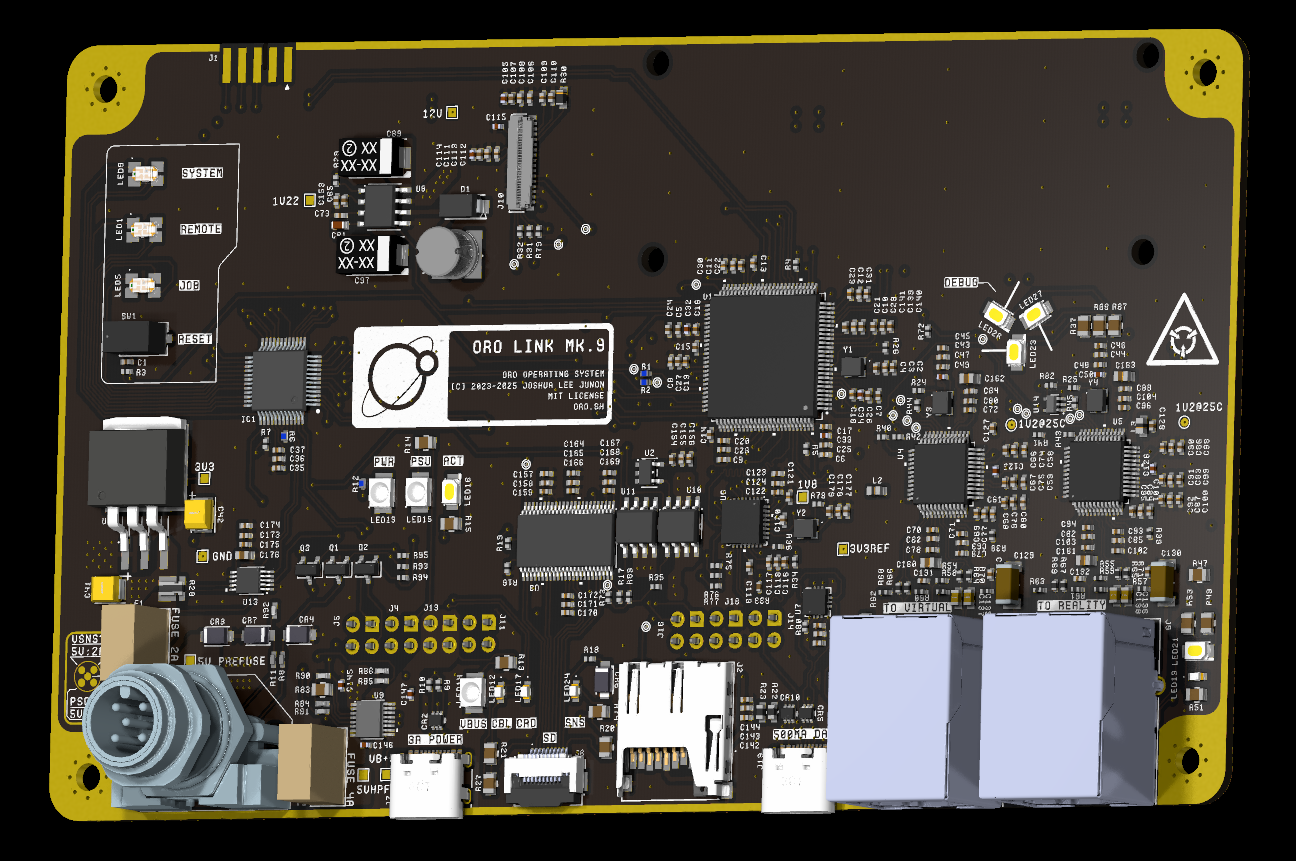
This is the Oro Link project, a set of custom PCBs, firmware, and server infrastructure for the testing of the Oro Operating System via CI/CD pipelines.
The link is a physical board that interfaces with the ports and headers of supported computers, devices, and boards, and runs firmware to obtain builds of the Oro kernel and associated modules to send to the System Under Test (SUT) for automated testing and reporting.
Sd adapter bill of materials (BOM)
13 components, 6 distinct parts.
| Qty | Part | Footprint | Refs |
|---|---|---|---|
| 2 | CLM3C-WKW-CXAYA453 | CLM3CWKWCXAYA453 | LED1, LED2 |
| 1 | BLM18PG221SN1D | IND_BLM18_0603_MUR | L1 |
| 2 | 1u | cap_UMK105 CG080CV-F_TAY | C1, C4 |
| 1 | 0.1u | CAP_MSAS1L-3_TAY | C2 |
| 1 | 0.01u | CAP_0402_N_WAL | C3 |
| 6 | 33R | RES_0510_SUS | R1, R2, R3, R4, R5, R6 |
Sd adapter design files
The KiCad project lives in the oro-os/link repository on GitHub; these links point at the commit this page was built from.
Sd adapter: common questions
How big is the Sd adapter PCB?
The Sd adapter measures 11 × 45.1 mm, has 2 copper layers and is 1.6 mm thick.
How many components are on the Sd adapter?
13 components, from 6 distinct parts. The full bill of materials is listed on this page.
Where can I download the Sd adapter design files?
From the oro-os/link repository on GitHub, which has the KiCad layout and the schematic; the links under Design files point to each one.
Can I use the Sd adapter design in my own project?
Yes, under the terms of its MIT license, which oro-os chose for the repository.