
Gate Driver Circuit Design

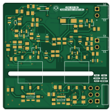
About the Gate Driver Circuit Design PCB
Gate Driver Circuit Design is an open source PCB design by pawardaksh, published on GitHub. It is a 2-layer board measuring 40.3 × 40.7 mm, with 105 components from 43 distinct parts.
Other key parts include the SN6501QDBVRQ1, TPS7B6950QDCYRQ1, TL431AQDBZRQ1, UCC21530QDWKRQ1 and ISO7721QDRQ1. By type, the board carries 43 capacitors, 35 resistors, 9 ICs, 9 diodes, 4 transistors and 3 connectors.
From the project
TI gate driver for MOSFET and IGBT created using KiCad
Main components on the Gate Driver Circuit Design
Gate Driver Circuit Design bill of materials (BOM)
105 components, 43 distinct parts — part numbers from the project's BOM.
| Qty | Part | Footprint | Refs |
|---|---|---|---|
| 2 | SN6501QDBVRQ1 Texas Instruments | SOT95P280X145-5N | U1, U4 |
| 1 | TPS7B6950QDCYRQ1 Texas Instruments | VREG_TPS7B6950QDCYRQ1 | U2 |
| 3 | TL431AQDBZRQ1 Texas Instruments | DBZ3 | U3, U5, U9 |
| 1 | UCC21530QDWKRQ1 Texas Instruments | UCC21530QDWKRQ1 | U6 |
| 1 | ISO7721QDRQ1 Texas Instruments | SOIC127P600X175-8N | U7 |
| 1 | LMV762QMA/NOPB LMV762QMA_NOPB Texas Instruments | SOIC127P600X175-8N | U8 |
| 1 | 30V CSD17313Q2 Texas Instruments | TRANS_CSD17313Q2 | Q1 |
| 3 | MMBT3904T-7-F Diodes Inc. | SOT50P160X90-3N | Q2, Q3, Q4 |
| 1 | 90122-0763 Molex | MOLEX_90122-0763 | J101 |
| 2 | 90121-0762 Molex | HDRRA2W64P0X254_1X2_508X250X360P | J102, J103 |
| 2 | 750343725 Wurth Elektronik | TRANSFORMER_750343725_WRE-L | T1, T2 |
| 2 | 70V BAV70-E3-08 Vishay-Semiconductor | SOT_70-E3-08_VIS | D1, D2 |
| 2 | MBRA340T3G ON Semiconductor | DIOM5226X220N | D3, D4 |
| 3 | 1N4148X-TP Micro Commercial | SODFL1608X70N | D5, D7, D8 |
| 1 | BYG23T-M3/TR Vishay-Semiconductor | DIOM5127X229N | D6 |
| 1 | BZT52C5V1-G3-08 5.1V Vishay-Semiconductor | SOD3716X135N | D9 |
| 17 | 0805B104K250CT 0.1µF | CAPC2012X90N | C1, C3, C6, C8, C9, C11, C14, C15 +9 |
| 2 | LMK212ABJ106KGHT 10µF TAIYO YUDEN | CAPC2012X135N | C2, C10 |
| 9 | GRT21BR61H475KE13L 4.7µF | GRT21BR61E226ME13L | C4, C5, C7, C12, C13, C16, C18, C26 +1 |
| 4 | GRM2195C1H103JA01D 0.01µF Murata Electronics | CAPC2012X95N | C20, C21, C30, C31 |
Show 23 more
| Qty | Part | Footprint | Refs |
|---|---|---|---|
| 2 | AC0805KRX7R8BB104 0.1µF YAGEO | CAPC2012X95N | C23, C24 |
| 1 | CC0805JRNPO9BN270 27pF YAGEO | CAPC2012X70N | C34 |
| 1 | CL21C101JBANNNC 100µF Samsung Electro-Mechanic | CAPC2012X75N | C35 |
| 1 | C0805C471J5GACTU 470pF KEMET | C0805 | C36 |
| 4 | C0805C101J1GACAUTO 100pF KEMET | C0805 | C38, C41, C42, C43 |
| 2 | C0805C102K5RACAUTO 1000pF KEMET | C0805 | C39, C40 |
| 2 | CRCW08054K70JNEA 4.7k Vishay-Dale | RESC2012X50N | R1, R4 |
| 2 | RT0805DRE073K01L 3.01k Yageo America | RESC2012X60N | R2, R5 |
| 2 | RR1220P-4991-D-M 4.99k Susumu | RESC2013X65N | R3, R6 |
| 2 | CRCW12065R11FKEA 5.11 Vishay-Dale | RESC3216X60N | R7, R10 |
| 2 | CRM1206-JW-1R0ELF 1.0 Bourns | RESC3116X65N | R8, R11 |
| 1 | CR0805-F/-1R00ELF 1k Bourns | RESC2012X60N | R9 |
| 2 | CRCW080510K0FKEBC 10.0k Vishay-Dale | RESC2012X60N | R12, R14 |
| 1 | CRCW120627R0JNEA 27 Vishay-Dale | RESC3216X60N | R13 |
| 7 | CR0805-FX-5101ELF 5.1k | RESC2012X60N | R15, R20, R23, R25, R26, R30, R32 |
| 4 | RC0805JR-131KL 1.0k YAGEO | RESC2012X60N | R16, R17, R19, R27 |
| 1 | ERA-6AEB103V 10.0k Panasonic | RESC2012X60N | R18 |
| 1 | RMC1/16K102FTP 1.00k Kamaya | RESC2012X60N | R21 |
| 1 | CR0805JW-222ELF 2.2k Bourns | RESC2012X60N | R22 |
| 1 | RNCP0805FTD2K00 2.00k SEI Stackpole | RESC2012X60N | R24 |
| 1 | RNCF0805DTE10K0 10.0k SEI Stackpole | RESC2012X60N | R28 |
| 1 | CRCW080515K0JNEA 15k Vishay / Dale | RESC2012X50N | R29 |
| 4 | ERJ-U060R00V 0 Panasonic | RESC2012X60N | R31, R33, R34, R132 |
Gate Driver Circuit Design design files
The KiCad project lives in the pawardaksh/TI_Gate_Driver_Daksh repository on GitHub; these links point at the commit this page was built from.
Gate Driver Circuit Design: common questions
How big is the Gate Driver Circuit Design PCB?
The Gate Driver Circuit Design measures 40.3 × 40.7 mm, has 2 copper layers and is 1.6 mm thick.
How many components are on the Gate Driver Circuit Design?
105 components, from 43 distinct parts, with part numbers taken from the project's own BOM. The full bill of materials is listed on this page.
Where can I download the Gate Driver Circuit Design design files?
From the pawardaksh/TI_Gate_Driver_Daksh repository on GitHub, which has the KiCad layout, the schematic and the BOM; the links under Design files point to each one.
Can I use the Gate Driver Circuit Design design in my own project?
The repository has no license, so all rights stay with pawardaksh. Use it as a reference, and ask the author before reusing the design.