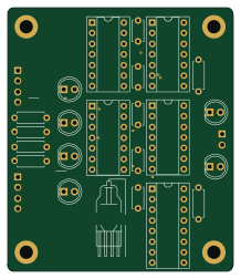
Add sub module tester

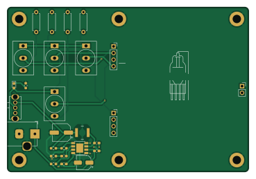
About the Add sub module tester
Add sub module tester is an open source PCB design by phurd22, published on GitHub. It is a 2-layer board measuring 92 × 63 mm, with 27 components from 18 distinct parts.
Other key parts include the Toggle_Switch_3PIN and AP6503. By type, the board carries 9 resistors, 6 capacitors, 5 ICs, 4 connectors, 1 switch and 1 diode.
From the project
Developed by ABCm Development Group (formerly SDMAY25-29 Senior Design) under Dr. Alexander Stoytchev, the ABCm is a modern reimagining of the orignal Atanasoff-Berry Computer.
Developed by ABCm Development Group (formerly SDMAY25-29 Senior Design) under Dr. Alexander Stoytchev, the ABCm is a modern reimagining of the orignal Atanasoff-Berry Computer.
Built by Dr. Atanasoff and Clifford Berry in 1939, the Atanasoff Berry Computer (ABC) was the first digital electronic computer ever built, and the ABCm seeks to recreate the magic of this device using modern technology and design techniques. This repository houses all the final materials of the project including KiCAD projects, microcontroller and Android scripts, and supplemental documentation.

Main components on the Add sub module tester
Add sub module tester bill of materials (BOM)
27 components, 18 distinct parts.
| Qty | Part | Footprint | Refs |
|---|---|---|---|
| 4 | Toggle_Switch_3PIN | SW-TH_MT-0-103-A101-M200-RS | U1, U2, U3, U4 |
| 1 | AP6503 | Diodes_SO-8EP | U5 |
| 2 | Conn_01x04_Socket | PinSocket_1x04_P2.54mm_Vertical | J1, J2 |
| 1 | 12V In | BarrelJack_Horizontal | J3 |
| 1 | Conn_01x02_Socket | PinSocket_1x02_P2.54mm_Vertical | J4 |
| 1 | PWR_SW | SW-TH_SK12D07VG5 | SW1 |
| 1 | PWR_Indicator | LED_0603_1608Metric_Pad1.05x0.95mm_HandSolder | D1 |
| 1 | 10uH | L_Coilcraft_LPS5030 | L1 |
| 1 | 22uF | CP_Elec_5x5.4 | C1 |
| 3 | 0.1uF | C_0603_1608Metric_Pad1.08x0.95mm_HandSolder | C2, C3, C4 |
| 1 | 6.8nF | C_0603_1608Metric_Pad1.08x0.95mm_HandSolder | C5 |
| 1 | 47uF | CP_Elec_6.3x7.7 | C6 |
| 4 | 330 | R_Axial_DIN0207_L6.3mm_D2.5mm_P7.62mm_Horizontal | R1, R2, R3, R4 |
| 1 | 100k | R_0603_1608Metric_Pad0.98x0.95mm_HandSolder | R5 |
| 1 | 6.8k | R_0603_1608Metric_Pad0.98x0.95mm_HandSolder | R6 |
| 1 | 45.3k | R_0603_1608Metric_Pad0.98x0.95mm_HandSolder | R7 |
| 1 | 10k | R_0603_1608Metric_Pad0.98x0.95mm_HandSolder | R8 |
| 1 | 330 | R_0603_1608Metric_Pad0.98x0.95mm_HandSolder | R9 |
Add sub module tester design files
The KiCad project lives in the phurd22/ABCm repository on GitHub; these links point at the commit this page was built from.
Add sub module tester: common questions
How big is the Add sub module tester?
The Add sub module tester measures 92 × 63 mm, has 2 copper layers and is 1.6 mm thick.
How many components are on the Add sub module tester?
27 components, from 18 distinct parts. The full bill of materials is listed on this page.
Where can I download the Add sub module tester design files?
From the phurd22/ABCm repository on GitHub, which has the KiCad layout and the schematic; the links under Design files point to each one.
Can I use the Add sub module tester design in my own project?
The repository has no license, so all rights stay with phurd22. Use it as a reference, and ask the author before reusing the design.