
Srambo 1

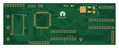
About the Srambo 1 PCB
Srambo 1 is an open source PCB design by piotr-wiszowaty, published on GitHub under the GPL-3.0 license. It is a 2-layer board measuring 113 × 42 mm, with 29 components from 21 distinct parts.
Other key parts include the XC9572XL-TQ100, AP1117E33 and AS6C4008. By type, the board carries 14 connectors, 10 capacitors, 3 ICs, 1 diode and 1 resistor.
From the project
320 kB Atari XE memory expansion
srambo\_1 is a yet another 320 kB Atari XE memory expansion. It designed for Atari 130 XEs and 65 XEs with ECI connector.
The device has two modes of operation (selected with a jumper):
1. 'Rambo' - extended memory banks are selected with PORTB bits 2, 3, 5, 6. Access to extended memory by both CPU and ANTIC is controlled with PORTB bit 4. To turn on this mode one needs to connect pins AUX3 and AUX4 together. 2. 'Compy' - extended memory banks are selected with PORTB bits 2, 3, 6, 7. Access to extended memory by CPU is controlled with PORTB bit 4. Access to extended memory by ANTIC is…
Main components on the Srambo 1
Srambo 1 bill of materials (BOM)
29 components, 21 distinct parts.
| Qty | Part | Footprint | Refs |
|---|---|---|---|
| 1 | XC9572XL-TQ100 | TQFP-100_14x14mm_Pitch0.5mm | U1 |
| 1 | AP1117E33 | TO-252-2Lead | U2 |
| 1 | AS6C4008 | TSOP-II-32_21.0x10.2mm_Pitch1.27mm | U3 |
| 1 | JTAG | Pin_Header_Straight_1x06 | P1 |
| 1 | GND | Pin_Header_Straight_1x01 | P2 |
| 1 | AUX_B | Pin_Header_Straight_1x02 | P3 |
| 1 | AUX_A | Pin_Header_Straight_1x05 | P4 |
| 1 | DATA5-7 | Pin_Header_Straight_1x03 | P5 |
| 1 | DATA1 | Pin_Header_Straight_1x01 | P6 |
| 1 | DATA2 | Pin_Header_Straight_1x01 | P7 |
| 1 | DATA3 | Pin_Header_Straight_1x01 | P8 |
| 1 | DRAM_LEFT | Pin_Header_Straight_1x08 | P9 |
| 1 | EMMU_LEFT | Pin_Header_Straight_1x10 | P10 |
| 1 | MMU_LEFT | Pin_Header_Straight_1x10 | P11 |
| 1 | DRAM_RIGHT | Pin_Header_Straight_1x08 | P12 |
| 1 | EMMU_RIGHT | Pin_Header_Straight_1x10 | P13 |
| 1 | MMU_RIGHT | Pin_Header_Straight_1x10 | P14 |
| 1 | LED | LED_0805 | D1 |
| 8 | 100 nF | C_0805_HandSoldering | C1, C2, C3, C4, C5, C7, C8, C10 |
| 2 | 10 uF | TantalC_SizeB_EIA-3528_HandSoldering | C6, C9 |
Show 1 more
| Qty | Part | Footprint | Refs |
|---|---|---|---|
| 1 | 1k | R_0805_HandSoldering | R1 |
Srambo 1 design files
The KiCad project lives in the piotr-wiszowaty/srambo_1 repository on GitHub; these links point at the commit this page was built from.
- Layoutpcb/srambo_1.kicad_pcb
Srambo 1: common questions
How big is the Srambo 1 PCB?
The Srambo 1 measures 113 × 42 mm, has 2 copper layers and is 1.6 mm thick.
How many components are on the Srambo 1?
29 components, from 21 distinct parts. The full bill of materials is listed on this page.
Where can I download the Srambo 1 design files?
From the piotr-wiszowaty/srambo_1 repository on GitHub, which has the KiCad layout; the links under Design files point to each one.
Can I use the Srambo 1 design in my own project?
Yes, under the terms of its GPL-3.0 license, which piotr-wiszowaty chose for the repository.