
AvaotaA1

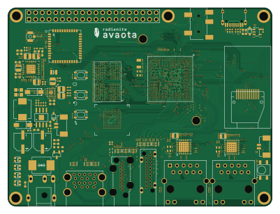
About the AvaotaA1 PCB
AvaotaA1 is an open source PCB design by RadianiteComputers, published on GitHub. It is a 8-layer board measuring 100 × 75 mm, with 489 components from 50 distinct parts.
By type, the board carries 286 capacitors, 118 resistors, 30 diodes, 15 ICs, 10 inductors and 5 LEDs.
From the project
A collection of Radianite boards we have designed so far. All are licensed under CC BY-SA 4.0
2. Open the .kicadpro` file on either project you want to help in. 3. Edit, edit, edit! 4. Commit with your changes. Make sure your commit messages are concise! 5. Finally, create a pull request. A member will look after your design. There are criterias taken into account: - Legibility and form factor - Trace lengths and signal integrity (advanced computers only like Project Lemon Irvine) - Overall impedance (including RF) - Possibility for EMI or crosstalks (<1% to be accepted, almost no EMI or crosstalks)
AvaotaA1 bill of materials (BOM)
489 components, 50 distinct parts.
| Qty | Part | Footprint | Refs |
|---|---|---|---|
| 2 | — ROQANG(容强) | CAP-SMD_BD6.3-L6.6-W6.6-LS7.6-RD | U1, U2 |
| 1 | — TI(德州仪器) | SOIC-8_L5.0-W4.0-P1.27-LS6.0-BL-EP2.0 | U3 |
| 1 | — | QFN-52_L6.0-W6.0-P0.40-BL-EP3.4-1 | U4 |
| 1 | — | QFN-20_L3.0-W3.0-P0.40-BL-EP1.5 | U5 |
| 1 | — Kingston(金士顿) | FBGA-153_L13.0-W11.5 | U8 |
| 1 | — | LGA-44_L12.0-W12.0-P0.90 | U9 |
| 1 | — Tokmas(托克马斯) | SOP-8_L4.9-W3.9-P1.27-LS6.0-BL | U11 |
| 2 | — REALTEK(瑞昱) | WQFN-40_L5.0-W5.0-P0.4-BL-EP | U12, U13 |
| 1 | — | T527-BGA664 | U14 |
| 1 | — | DP_TH_SIDE_VERTICAL | U15 |
| 2 | — silergy(矽力杰) | SOT-23-5_L3.0-W1.7-P0.95-LS2.8-BL | U16, U17 |
| 1 | — WINBOND(华邦) | WSON-8_L8.0-W6.10-P1.27-BL-EP | U18 |
| 1 | — YANGJIE(扬杰) | SOT-23-3_L2.9-W1.3-P1.90-LS2.4-BR | Q1 |
| 3 | — HD(浩都频率) | crystal-smd_4p-l2.0-w1.6-bl-nsk | X1, X3, X4 |
| 1 | — EPSON(爱普生) | osc-smd_l3.2-w1.5 nsk | X2 |
| 1 | — XKB Connectivity(中国星坤) | AUDIO-SMD_PJ-327A0-SMT | CN2 |
| 2 | — MOLEX | CONN-SMD_2P-P1.25_053398-0X71 | CN3, CN4 |
| 1 | — EVERLIGHT(亿光) | SENSOR-SMD_IRM-H638T-TR2-TL | CGQ1 |
| 1 | — XUNPU(讯普) | DC-IN-TH_DC-044A-20A | DC1 |
| 3 | — DGBZ(东莞博众) | SW-SMD_4P-L4.2-W3.4-P2.15-LS4.5-TL | FEL1, PWR1, RESET1 |
Show 30 more
| Qty | Part | Footprint | Refs |
|---|---|---|---|
| 1 | — XUNPU(讯普) | FPC-SMD_50P-P0.50_FPC-05FB-50PH20 | FPC1 |
| 1 | — XUNPU(讯普) | FPC-SMD_30P-P0.50_FPC-05FB-30PH20 | FPC2 |
| 1 | — JILN(锦凌) | HDR-TH_40P-P2.54-V-M-R2-C20-S2.54 | H1 |
| 1 | — BAT WIRELESS(蝙蝠无线) | IPEX-SMD_BWIPX-1-001E | RF1 |
| 2 | — HANRUN(汉仁) | RJ45-TH_HR911130A | RJ1, RJ2 |
| 1 | — MOLEX | SIM-SMD_8P-1040310811 | SIM1 |
| 1 | — | TFT_1.14寸_0.7MM-13P | TFT1 |
| 1 | — | BGA200P65_80B1000_1500H90 | UD1 |
| 1 | — XUNPU(讯普) | HDMI-SMD_HDMI-001C | USB1 |
| 1 | — XUNPU(讯普) | USB-A-TH_XUNPU_USB-303WSD-BRY | USB2 |
| 1 | — XUNPU | USB-C-SMD_TYPEC-304-BCP16-1 | USB3 |
| 1 | — | RGBLED_0807 | LED1 |
| 4 | — worldsemi | LED-SMD_4P-L2.0-W2.0-TL_WS2812B-2020 | LED2, LED3, LED4, LED5 |
| 2 | — Hottech(合科泰) | SOD-323_L1.8-W1.3-LS2.5-RD | D1, D32 |
| 1 | — 晶导微电子 | SMC_L6.9-W5.9-LS7.9-BI | D2 |
| 2 | — MDD | SMA_L4.4-W2.8-LS5.4-R-RD | D3, D4 |
| 9 | — SEMTECH | SLP2510P8_L2.5-W1.0-P0.50-BL | D5, D6, D8, D10, D11, D12, D13, D14 +1 |
| 2 | — BORN(伯恩半导体) | SOD-523_L1.2-W0.8-LS1.6-RD-1 NSK | D7, D9 |
| 14 | — BORN伯恩半导体 | d0402 | D16, D17, D18, D19, D20, D21, D22, D23 +6 |
| 1 | — cjiang(长江微电) | IND-SMD_L7.0-W6.6 | L1 |
| 7 | — TDK | ind-smd_l2.0-w1.6_1 | L2, L3, L4, L5, L6, L7, L8 |
| 2 | — Sunlord(顺络) | IND-SMD_L2.0-W1.6 | L9, L10 |
| 21 | — | C0603-NSK | C1, C2, C3, C7, C8, C27, C28, C44 +13 |
| 35 | — | c0402-nsk | C4, C9, C10, C15, C16, C18, C25, C26 +27 |
| 2 | — | C0805 NSK | C5, C6 |
| 225 | — FH(风华) | c0201 nsk | C11, C12, C13, C14, C17, C19, C20, C21 +217 |
| 3 | — | C1206 | C248, C255, C294 |
| 2 | — | R0603 NSK | R1, R2 |
| 8 | — | R0402-NSK | R3, R4, R5, R6, R7, R8, R28, R126 |
| 108 | — | r0201 nsk | R9, R10, R11, R12, R13, R14, R17, R19 +100 |
AvaotaA1 design files
The KiCad project lives in the RadianiteComputers/RadianiteBoards repository on GitHub; these links point at the commit this page was built from.
AvaotaA1: common questions
How big is the AvaotaA1 PCB?
The AvaotaA1 measures 100 × 75 mm, has 8 copper layers and is 1.599998 mm thick.
How many components are on the AvaotaA1?
489 components, from 50 distinct parts. The full bill of materials is listed on this page.
Where can I download the AvaotaA1 design files?
From the RadianiteComputers/RadianiteBoards repository on GitHub, which has the KiCad layout and the schematic; the links under Design files point to each one.
Can I use the AvaotaA1 design in my own project?
The repository has no license, so all rights stay with RadianiteComputers. Use it as a reference, and ask the author before reusing the design.
More boards in RadianiteBoards
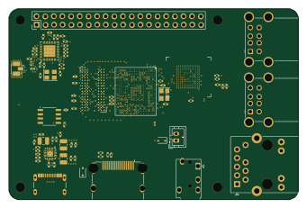
Radianite-ProjectLemonIrvine
85 × 56 mm173 parts6LNo license0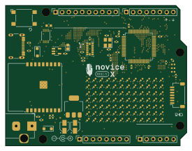 ESP32
ESP32Radianite-Novice-RISCV-X
68.6 × 53.3 mm134 parts2LNo license0 ESP32
ESP32Radianite-MicroNeo2
50 × 33 mm70 parts4LNo license0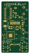 RP2040/RP2350
Radianite uFM
24 × 45 mm62 parts4LNo license0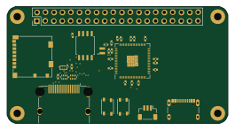 RP2040/RP2350
Radiante-Lite-Gen2
66 × 35 mm58 parts2LNo license0 ESP32
ESP32Radianite-Buddy2
20 × 52 mm58 parts4LNo license0 ESP32
ESP32Radianite-Schtick
22 × 65 mm50 parts4LNo license0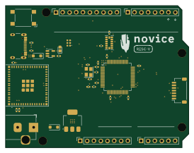 ESP32
ESP32Radianite-Novice-RISCV
68.5 × 53.3 mm40 parts2LNo license0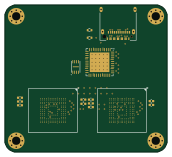
Radianite-VariablePortableSSD
43 × 39 mm39 parts4LNo license0