
Fault injection interposer

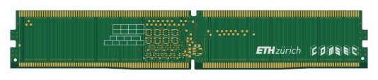
About the Fault injection interposer PCB
Fault injection interposer is an open source PCB design by refault-artifacts, published on GitHub under the MIT license. It is a 6-layer board measuring 133.4 × 21.9 mm, with 119 components from 58 distinct parts.
Other key parts include the DDR5, 90414-15011-21, TLV71211, TMUX136 and PI5A3157CEX. By type, the board carries 78 test points, 35 ICs, 3 capacitors, 1 connector, 1 diode and 1 resistor.
From the project
Hardware design files of the fault injection interposer used in REFault: A Fault Injection Platform for Rowhammer Research on DDR5 Memory.
The interposer consists of a 6-layer PCB that can be used in between an off-the-shelf DDR5-compatible motherboard and an DDR5 SDRAM UDIMM. Some signals can be forced high or low by an external control signal to inject or suppress certain DRAM commands.
For convenience, you can also find a PDF version of the schematic in docs/schematic.pdf. A bill of materials (BOM) is also provided in docs.
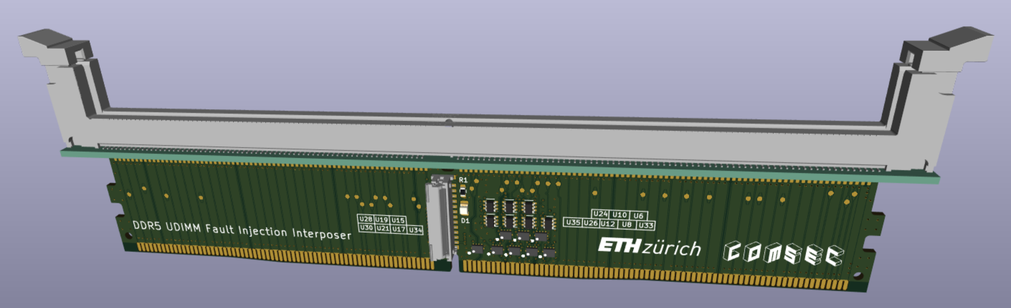
Main components on the Fault injection interposer
Fault injection interposer bill of materials (BOM)
119 components, 58 distinct parts — part numbers from the project's BOM.
| Qty | Part | Footprint | Refs |
|---|---|---|---|
| 1 | DDR5 | ddr5_edge_connector | U1 |
| 1 | 90414-15011-21 UMAX 90414-15011-21 UMAX | ddr5_bottom_conn_double | U2 |
| 1 | TLV71211 TLV71211_SOT23-5 Texas Instruments | SOT-23-5 | U3 |
| 17 | TMUX136 Texas Instruments | uqfn10 | U4, U5, U6, U7, U8, U9, U10, U11 +9 |
| 15 | PI5A3157CEX ~ Diodes Inc | SOT-363_SC-70-6 | U13, U14, U15, U16, U17, U18, U19, U20 +7 |
| 1 | 501951-2430 Molex 5019512430 Molex | 5019512430 | J1 |
| 1 | VIN_BULK | testpoint | TP1 |
| 1 | HSCL | testpoint | TP2 |
| 1 | HSDA | testpoint | TP3 |
| 23 | VSS | testpoint | TP4, TP6, TP9, TP12, TP15, TP17, TP20, TP23 +15 |
| 1 | CS0_A_n | testpoint | TP5 |
| 1 | CA0_A | testpoint | TP7 |
| 1 | CA2_A | testpoint | TP8 |
| 1 | CA4_A | testpoint | TP10 |
| 1 | CA6_A | testpoint | TP11 |
| 1 | CA8_A | testpoint | TP13 |
| 1 | CA10_A | testpoint | TP14 |
| 1 | CA12_A | testpoint | TP16 |
| 1 | CK0_A_t | testpoint | TP18 |
| 1 | CK0_A_c | testpoint | TP19 |
Show 38 more
| Qty | Part | Footprint | Refs |
|---|---|---|---|
| 1 | CK0_B_t | testpoint | TP21 |
| 1 | CK0_B_c | testpoint | TP22 |
| 1 | CA12_B | testpoint | TP24 |
| 1 | CA10_B | testpoint | TP25 |
| 1 | CA8_B | testpoint | TP26 |
| 1 | CA6_B | testpoint | TP28 |
| 1 | CA4_B | testpoint | TP29 |
| 1 | CA2_B | testpoint | TP30 |
| 1 | CA0_B | testpoint | TP31 |
| 1 | CS0_B_n | testpoint | TP32 |
| 1 | RESET_n | testpoint | TP34 |
| 1 | PWR_GD | testpoint | TP35 |
| 1 | HSA | testpoint | TP36 |
| 1 | PWR_EN | testpoint | TP38 |
| 1 | ALERT_n | testpoint | TP39 |
| 1 | CS1_A_n | testpoint | TP40 |
| 1 | CA1_A | testpoint | TP41 |
| 1 | CA3_A | testpoint | TP42 |
| 1 | CA5_A | testpoint | TP44 |
| 1 | CA7_A | testpoint | TP45 |
| 1 | CA9_A | testpoint | TP47 |
| 1 | CA11_A | testpoint | TP48 |
| 1 | CK1_A_t | testpoint | TP51 |
| 1 | CK1_A_c | testpoint | TP53 |
| 1 | CK1_B_t | testpoint | TP56 |
| 1 | CK1_B_c | testpoint | TP57 |
| 1 | CA11_B | testpoint | TP59 |
| 1 | CA9_B | testpoint | TP60 |
| 1 | CA7_B | testpoint | TP62 |
| 1 | CA5_B | testpoint | TP63 |
| 1 | CA3_B | testpoint | TP65 |
| 1 | CA1_B | testpoint | TP66 |
| 1 | CS1_B_n | testpoint | TP68 |
| 9 | tp | testpoint_small | TP70, TP71, TP83, TP84, TP85, TP86, TP87, TP88 +1 |
| 1 | APHCM2012CGCK-F01 generic | LED_0805_2012Metric | D1 |
| 2 | 100N 100n generic | C_0603_1608Metric | C1, C3 |
| 1 | 2.2U 2.2u generic | C_0603_1608Metric | C2 |
| 1 | 330 generic | R_0603_1608Metric | R1 |
Fault injection interposer design files
The KiCad project lives in the refault-artifacts/fault-injection-interposer repository on GitHub; these links point at the commit this page was built from.
Fault injection interposer: common questions
How big is the Fault injection interposer PCB?
The Fault injection interposer measures 133.4 × 21.9 mm, has 6 copper layers and is 1.1064 mm thick.
How many components are on the Fault injection interposer?
119 components, from 58 distinct parts, with part numbers taken from the project's own BOM. The full bill of materials is listed on this page.
Where can I download the Fault injection interposer design files?
From the refault-artifacts/fault-injection-interposer repository on GitHub, which has the KiCad layout, the schematic and the BOM; the links under Design files point to each one.
Can I use the Fault injection interposer design in my own project?
Yes, under the terms of its MIT license, which refault-artifacts chose for the repository.