
Adjustable-Synchronous-Buck-Converter

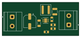
About the Adjustable-Synchronous-Buck-Converter PCB
Adjustable-Synchronous-Buck-Converter is an open source PCB design by ryanli04, published on GitHub. It is a 2-layer board measuring 41.8 × 18.3 mm, with 11 components from 10 distinct parts.
Other key parts include the LTC3624EDD-PBF. By type, the board carries 4 capacitors, 3 resistors, 2 connectors, 1 IC and 1 inductor.
It belongs with the power & battery and displays & leds designs in this gallery.
From the project
A personal project to learn power electronics and PCB design by building a synchronous buck converter in three phases: a fixed 5 V supply, then an adjustable output, then a display that shows live measurements.
A personal project to learn power electronics and PCB design by building a synchronous buck converter in three phases: a fixed 5 V supply, then an adjustable output, then a display that shows live measurements.
Designed in KiCad 10 around the Analog Devices LTC3624, a 17 V, 2 A synchronous step-down regulator with both power MOSFETs built in.
Phase 1: layout complete, next step is simulation.
Main components on the Adjustable-Synchronous-Buck-Converter
Adjustable-Synchronous-Buck-Converter bill of materials (BOM)
11 components, 10 distinct parts.
| Qty | Part | Footprint | Refs |
|---|---|---|---|
| 1 | LTC3624EDD-PBF | DFN-8-1EP_3x3mm_P0.5mm_EP1.66x2.38mm | U1 |
| 2 | Screw_Terminal_01x02 | TerminalBlock_Phoenix_MKDS-1,5-2-5.08_1x02_P5.08mm_Horizontal | J1, J2 |
| 1 | 4.7uH | L_Coilcraft_XAL5030-XXX | L1 |
| 1 | 47uF | CP_Elec_6.3x7.7 | C1 |
| 1 | 10uF | C_1206_3216Metric | C2 |
| 1 | 2.2uF | C_0805_2012Metric | C3 |
| 1 | 47uF | C_1210_3225Metric | C4 |
| 1 | 73.2K | R_0805_2012Metric | R1 |
| 1 | 10K | R_0805_2012Metric | R2 |
| 1 | 100K | R_0805_2012Metric | R3 |
Adjustable-Synchronous-Buck-Converter design files
The KiCad project lives in the ryanli04/Adjustable-Synchronous-Buck-Converter repository on GitHub; these links point at the commit this page was built from.
Adjustable-Synchronous-Buck-Converter: common questions
How big is the Adjustable-Synchronous-Buck-Converter PCB?
The Adjustable-Synchronous-Buck-Converter measures 41.8 × 18.3 mm, has 2 copper layers and is 1.6 mm thick.
How many components are on the Adjustable-Synchronous-Buck-Converter?
11 components, from 10 distinct parts. The full bill of materials is listed on this page.
Where can I download the Adjustable-Synchronous-Buck-Converter design files?
From the ryanli04/Adjustable-Synchronous-Buck-Converter repository on GitHub, which has the KiCad layout and the schematic; the links under Design files point to each one.
Can I use the Adjustable-Synchronous-Buck-Converter design in my own project?
The repository has no license, so all rights stay with ryanli04. Use it as a reference, and ask the author before reusing the design.
Similar boards
View base
scottbez1
81.2 × 81.2 mm81 parts2LApache-2.022.2k
BM28B0.6-24DSBreakout
15.2 × 35.6 mm3 parts2LApache-2.022.2k
LevelShifterBreakout
15.2 × 20.3 mm5 parts2LApache-2.022.2k
View screen
35 × 35 mm12 parts2LApache-2.022.2k
Display eval
byrantech
52.1 × 22.6 mm12 parts4LMIT4.3k
ChainlinkBase
98.4 × 190.5 mm119 parts2LApache-2.04.2k