
IO-Board

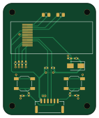
About the IO-Board
IO-Board is an open source PCB design by SimLinkModule, published on GitHub under the Apache-2.0 license. It is a 2-layer board measuring 35 × 41.9 mm, with 18 components from 10 distinct parts.
By type, the board carries 8 capacitors, 6 resistors, 2 switches, 1 connector and 1 diode.
It belongs with the displays & leds and iot & wireless designs in this gallery.
From the project
PCBs for a BLE game controller expansion module for the TBS Tango 2
There are 3 PCBs in this repo. The ConnectorBoard is responsible for the connection between the radio and the module. The MainBoard contains the ESP32 and a JST GH port for flashing. Flashing works in the same way as the ESP32 devkits with esptool.py. An additional USB-FTDI device is required for this. The IO board contains all the buttons and the display for the user. The PCB was divided into three parts to ensure that it can be installed in a shell as modularly as possible. Also, in the event of circuit faults, you don't have to order everything.
IO-Board bill of materials (BOM)
18 components, 10 distinct parts — part numbers from the project's BOM.
| Qty | Part | Footprint | Refs |
|---|---|---|---|
| 1 | CONN_01X06_MALE Conn_01x06_Male | JST_GH_SM06B-GHS-TB_1x06-1MP_P1.25mm_Horizontal | J1 |
| 2 | C202424 | SW_SPST_SKQG_WithStem | SW1, SW2 |
| 1 | SS14 | D_SMA | D1 |
| 2 | 1u | C_0805_2012Metric_Pad1.18x1.45mm_HandSolder | C1, C2 |
| 1 | 10U 10u | C_0402_1005Metric_Pad0.74x0.62mm_HandSolder | C3 |
| 1 | 2.2U 2.2u | C_0402_1005Metric_Pad0.74x0.62mm_HandSolder | C4 |
| 1 | 4.7U 4.7u | C_0402_1005Metric_Pad0.74x0.62mm_HandSolder | C5 |
| 3 | 0.1U 0.1u | C_0402_1005Metric_Pad0.74x0.62mm_HandSolder | C6, C7, C8 |
| 5 | 4.7K | R_0402_1005Metric | R1, R2, R3, R5, R6 |
| 1 | 560K | R_0402_1005Metric | R4 |
IO-Board design files
The KiCad project lives in the SimLinkModule/PCB repository on GitHub; these links point at the commit this page was built from.
IO-Board: common questions
How big is the IO-Board?
The IO-Board measures 35 × 41.9 mm, has 2 copper layers and is 1.6 mm thick.
How many components are on the IO-Board?
18 components, from 10 distinct parts, with part numbers taken from the project's own BOM. The full bill of materials is listed on this page.
Where can I download the IO-Board design files?
From the SimLinkModule/PCB repository on GitHub, which has the KiCad layout, the schematic and the BOM; the links under Design files point to each one.
Can I use the IO-Board design in my own project?
Yes, under the terms of its Apache-2.0 license, which SimLinkModule chose for the repository.
More boards in PCB
Similar boards
View base
scottbez1
81.2 × 81.2 mm81 parts2LApache-2.022.2k
BM28B0.6-24DSBreakout
15.2 × 35.6 mm3 parts2LApache-2.022.2k
LevelShifterBreakout
15.2 × 20.3 mm5 parts2LApache-2.022.2k
View screen
35 × 35 mm12 parts2LApache-2.022.2k
Display eval
byrantech
52.1 × 22.6 mm12 parts4LMIT4.3k
ChainlinkBase
98.4 × 190.5 mm119 parts2LApache-2.04.2k