
2-channel relay board hardware design

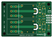
About the 2-channel relay board hardware design
2-channel relay board hardware design is an open source PCB design by SolderedElectronics, published on GitHub under the TAPR-OHL-1.0 license. It is a 2-layer board measuring 54 × 38 mm, with 30 components from 14 distinct parts.
Other key parts include the PC357_OPTO. By type, the board carries 9 resistors, 5 relays, 5 diodes, 3 jumpers, 2 ICs and 2 transistors.
From the project
Hardware design, BOM, gerbers and 3D files for 2-channel-relay-board designed by Soldered Electronics.
Did you ever wanted to turn on and off a device that needs large current or voltage? Whether operating on DC or AC, a relay is what you need. A relay is actually an electronic switch that is activated by a signal we send from a Dasduino or Arduino. This module further simplifies the whole process because it contains everything you need for the relay to work, and you just have to connect it to the microcontroller and power supply. You don’t have to think about voltages and currents, insulation between high and low voltage or grounding, everything is already taken care of on the board. This…

Main components on the 2-channel relay board hardware design
2-channel relay board hardware design bill of materials (BOM)
30 components, 14 distinct parts — part numbers from the project's BOM.
| Qty | Part | Footprint | Refs |
|---|---|---|---|
| 2 | PC357_OPTO | PC357_OPTO | U1, U2 |
| 2 | NPN-SOT-23-3 | SOT-23-3 | Q1, Q2 |
| 4 | HOLE_3.2mm | HOLE_3.2mm | H1, H2, H3, H4 |
| 3 | SMD-JUMPER-CONNECTED_TRACE_SLODERMASK | SMD-JUMPER-CONNECTED_TRACE_SLODERMASK | JP1, JP2, JP3 |
| 2 | SRD-05VDC-SL-C | SRD_RELAY_5V | K1, K4 |
| 2 | TERMINAL_KF235-5.0-3P | TERMINAL_KF235-5.0-3P | K2, K5 |
| 1 | HEADER_MALE_4X1 | HEADER_MALE_4X1 | K3 |
| 2 | blue | 0402LED | D1, D3 |
| 2 | M4_DIODA | M4_DIODA | D2, D4 |
| 1 | purple | 0402LED | D5 |
| 2 | 100R | 0603R | R1, R5 |
| 3 | 2k2 | 0402R | R2, R6, R9 |
| 2 | 330R | 0603R | R3, R7 |
| 2 | 10R | 0603R | R4, R8 |
2-channel relay board hardware design design files
The KiCad project lives in the SolderedElectronics/2-channel-relay-board-hardware-design repository on GitHub; these links point at the commit this page was built from.
2-channel relay board hardware design: common questions
How big is the 2-channel relay board hardware design?
The 2-channel relay board hardware design measures 54 × 38 mm, has 2 copper layers and is 1.6 mm thick.
How many components are on the 2-channel relay board hardware design?
30 components, from 14 distinct parts, with part numbers taken from the project's own BOM. The full bill of materials is listed on this page.
Where can I download the 2-channel relay board hardware design design files?
From the SolderedElectronics/2-channel-relay-board-hardware-design repository on GitHub, which has the KiCad layout, the schematic and the BOM; the links under Design files point to each one.
Can I use the 2-channel relay board hardware design design in my own project?
Yes, under the terms of its TAPR-OHL-1.0 license, which SolderedElectronics chose for the repository.