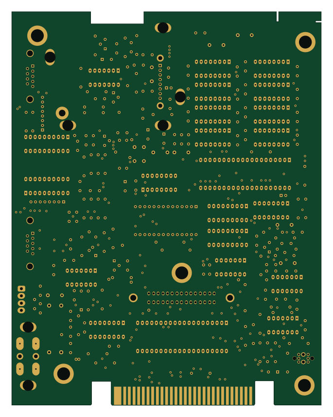
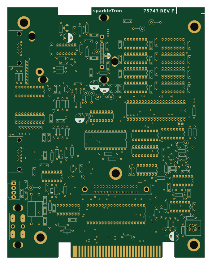
Sub rf mod

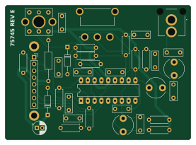
About the Sub rf mod PCB
Sub rf mod is an open source PCB design by sparkletron, published on GitHub under the MIT license. It is a 2-layer board measuring 69.1 × 50 mm, with 36 components from 26 distinct parts.
From the project
Reverse engineering the original Colecovision video game console.
details: Reverse engineer original PCB to create a schematic and functional replacment board. This only includes the NTSC system.
This recreation of the PCB is for documenation, and reproduction purposes. This mimicks the PCB of the original NTSC revision F main board.
Special thanks to ChildOfCV. Using his as a check for mine after buzzing out my own board was a great help. His schematic on its own is a great resource.

Sub rf mod bill of materials (BOM)
36 components, 26 distinct parts.
| Qty | Part | Footprint | Refs |
|---|---|---|---|
| 1 | Conn_01x08 | PinSocket_1x08_P2.54mm_Vertical | J4B1 |
| 1 | 1nF | C_Disc_D7.0mm_W2.5mm_P5.00mm | RF_C1 |
| 3 | 10nF | C_Disc_D7.0mm_W2.5mm_P5.00mm | RF_C2, RF_C3, RF_C8 |
| 3 | 47pF | C_Disc_D7.0mm_W2.5mm_P5.00mm | RF_C4, RF_C5, RF_C7 |
| 2 | 82pF | C_Disc_D7.0mm_W2.5mm_P5.00mm | RF_C6, RF_C9 |
| 1 | 10pF | C_Disc_D7.0mm_W2.5mm_P5.00mm | RF_C10 |
| 1 | 270pF | C_Disc_D7.0mm_W2.5mm_P5.00mm | RF_C11 |
| 1 | 20pF | C_Disc_D7.0mm_W2.5mm_P5.00mm | RF_C12 |
| 1 | 10uF | CP_Radial_D5.0mm_P2.00mm | RF_C13 |
| 1 | 1N753 | D_DO-35_SOD27_P10.16mm_Horizontal | RF_D1 |
| 1 | BB329A | D_DO-35_SOD27_P10.16mm_Horizontal | RF_D2 |
| 1 | RF_OUT | RCJ041_copy | RF_J1 |
| 1 | Jumper_2_Bridged | R_Axial_DIN0207_L6.3mm_D2.5mm_P15.24mm_Horizontal | RF_JP1 |
| 2 | 1.4uH | L_Radial_D7.5mm_P5.00mm_Fastron_07P | RF_L1, RF_L2 |
| 1 | 1.5uH | L_Radial_D7.5mm_P5.00mm_Fastron_07P | RF_L3 |
| 2 | 39K | R_Axial_DIN0207_L6.3mm_D2.5mm_P7.62mm_Horizontal | RF_R1, RF_R10 |
| 3 | 1K | R_Axial_DIN0207_L6.3mm_D2.5mm_P7.62mm_Horizontal | RF_R2, RF_R3, RF_R4 |
| 2 | 240R | R_Axial_DIN0207_L6.3mm_D2.5mm_P7.62mm_Horizontal | RF_R5, RF_R6 |
| 1 | 47R | R_Axial_DIN0207_L6.3mm_D2.5mm_P7.62mm_Horizontal | RF_R7 |
| 1 | 82R | R_Axial_DIN0207_L6.3mm_D2.5mm_P7.62mm_Horizontal | RF_R8 |
Show 6 more
| Qty | Part | Footprint | Refs |
|---|---|---|---|
| 1 | 8K2 | R_Axial_DIN0207_L6.3mm_D2.5mm_P7.62mm_Horizontal | RF_R9 |
| 1 | 4K7 | R_Axial_DIN0207_L6.3mm_D2.5mm_P7.62mm_Horizontal | RF_R11 |
| 1 | 15K | R_Axial_DIN0207_L6.3mm_D2.5mm_P7.62mm_Horizontal | RF_R12 |
| 1 | SW_SPDT | 1101M2S3ABE2 | RF_SW1 |
| 1 | LM1889 | DIP-18_W7.62mm_LongPads | RF_U1 |
| 1 | Sumida_73279 | Sumida_73279 | RF_VL1 |
Sub rf mod design files
The KiCad project lives in the sparkletron/righteous_tentacle_colecovision repository on GitHub; these links point at the commit this page was built from.
Sub rf mod: common questions
How big is the Sub rf mod PCB?
The Sub rf mod measures 69.1 × 50 mm, has 2 copper layers and is 1.6 mm thick.
How many components are on the Sub rf mod?
36 components, from 26 distinct parts. The full bill of materials is listed on this page.
Where can I download the Sub rf mod design files?
From the sparkletron/righteous_tentacle_colecovision repository on GitHub, which has the KiCad layout and the schematic; the links under Design files point to each one.
Can I use the Sub rf mod design in my own project?
Yes, under the terms of its MIT license, which sparkletron chose for the repository.