
Inertia simulation

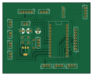
About the Inertia simulation PCB
Inertia simulation is an open source PCB design by superroket169, published on GitHub. It is a 2-layer board measuring 80 × 65 mm, with 22 components from 18 distinct parts.
Other key parts include the AMS1117-5.0 and pro_micro. By type, the board carries 6 switches, 5 capacitors, 4 connectors, 2 ICs, 1 LED and 1 resistor.
From the project
C++ vehicle simulation using raylib framework with hardware integration for G-force motion platforms.
2DOF motion simulator rig driven by DC motors.
- PC side: FlyPT Mover reads game telemetry and sends SMC3 frames ([A hi lo][B hi lo]) over serial. - firmware/: Arduino Nano (ATmega328P) controller in plain C: SMC3 parser, PID position loop, HOA/fault handling. Build with make, flash with make flash, run parser tests with make test. Rig-specific values are in firmware/config.h. - hardware/, mafsal/, BağlantıEkipmanları/: CAD and electronics files. - core/ (legacy): C++/raylib wheel input and Linux force-feedback experiments. Not part of the motion rig; kept for reference.
Main components on the Inertia simulation
Inertia simulation bill of materials (BOM)
22 components, 18 distinct parts — part numbers from the project's BOM.
| Qty | Part | Footprint | Refs |
|---|---|---|---|
| 1 | AMS1117-5.0 | SOT-223-3_TabPin2 | U1 |
| 1 | pro_micro | pro_micro | U2 |
| 1 | 12V | JST_EH_B2B-EH-A_1x02_P2.50mm_Vertical | J1 |
| 1 | Joystick | JST_EH_B8B-EH-A_1x08_P2.50mm_Vertical | J2 |
| 1 | USB_A | JST_EH_B4B-EH-A_1x04_P2.50mm_Vertical | J3 |
| 1 | pro_micro_usb | PinHeader_1x04_P2.54mm_Vertical | J4 |
| 3 | 10K | JST_EH_B3B-EH-A_1x03_P2.50mm_Vertical | Pot1, Pot2, Pot3 |
| 1 | BTN1 | JST_EH_B2B-EH-A_1x02_P2.50mm_Vertical | SW1 |
| 1 | BTN2 | JST_EH_B2B-EH-A_1x02_P2.50mm_Vertical | SW2 |
| 1 | BTN3 | JST_EH_B2B-EH-A_1x02_P2.50mm_Vertical | SW3 |
| 1 | RotaryEncoder_Switch | rotary_connector | SW4 |
| 1 | BTN4 | JST_EH_B2B-EH-A_1x02_P2.50mm_Vertical | SW5 |
| 1 | SW_DPDT_X2 SW_DPDT_x2 | JST_EH_B3B-EH-A_1x03_P2.50mm_Vertical | SW6 |
| 1 | WS2812B2 | JST_EH_B3B-EH-A_1x03_P2.50mm_Vertical | Led1 |
| 2 | 10UF 10uF | CP_Radial_D5.0mm_P2.50mm | C1, C4 |
| 2 | 100NF 100nF | C_Disc_D8.0mm_W2.5mm_P5.00mm | C2, C3 |
| 1 | 100UF 100uF | CP_Radial_D5.0mm_P2.50mm | C5 |
| 1 | 330 | R_Axial_DIN0207_L6.3mm_D2.5mm_P7.62mm_Horizontal | R1 |
Inertia simulation design files
The KiCad project lives in the superroket169/inertia-simulation repository on GitHub; these links point at the commit this page was built from.
Inertia simulation: common questions
How big is the Inertia simulation PCB?
The Inertia simulation measures 80 × 65 mm, has 2 copper layers and is 1.6 mm thick.
How many components are on the Inertia simulation?
22 components, from 18 distinct parts, with part numbers taken from the project's own BOM. The full bill of materials is listed on this page.
Where can I download the Inertia simulation design files?
From the superroket169/inertia-simulation repository on GitHub, which has the KiCad layout, the schematic and the BOM; the links under Design files point to each one.
Can I use the Inertia simulation design in my own project?
The repository has no license, so all rights stay with superroket169. Use it as a reference, and ask the author before reusing the design.