
Discharge Circuit

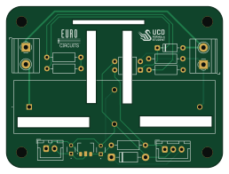
About the Discharge Circuit PCB
Discharge Circuit is an open source PCB design by UCDFS, published on GitHub. It is a 2-layer board measuring 64.4 × 47.9 mm, with 16 components from 11 distinct parts.
Other key parts include the MCP1703AT-3302E/MBVAO and HCPL-817-000E. By type, the board carries 5 resistors, 4 connectors, 2 ICs, 2 diodes, 2 capacitors and 1 relay.
From the project
KiCad projects and PCB designs for UCDFS electronic circuits.
Welcome to the University College Dublin Formula Student (UCDFS) KiCad circuits repository! This is the central location for all our electronic circuit designs, schematics, and PCB layouts.
This repository contains KiCad project files for various electronic circuits used in our Formula Student vehicle and projects. All designs are created using KiCad, an open-source electronic design automation (EDA) suite.
Main components on the Discharge Circuit
Discharge Circuit bill of materials (BOM)
16 components, 11 distinct parts — part numbers from the project's BOM.
| Qty | Part | Footprint | Refs |
|---|---|---|---|
| 1 | MCP1703AT-3302E/MBVAO | SOT-89-3 | U1 |
| 1 | HCPL-817-000E | DIP-4_W7.62mm | U2 |
| 2 | 1729128 Conn_01x02 | Phoenix_1x2_1729128 | J1, J2 |
| 1 | B2B-XH-A Conn_01x02 | JST_XH_B2B-XH-A_1x02_P2.50mm_Vertical | J3 |
| 1 | B3B-XH-A Conn_01x03 | JST_XH_B3B-XH-A_1x03_P2.50mm_Vertical | J4 |
| 1 | DBR71210 | DBR71210 | K1 |
| 1 | 1N4001 | D_DO-41_SOD81_P10.16mm_Horizontal | D1 |
| 1 | 1N4148 | D_DO-35_SOD27_P7.62mm_Horizontal | D3 |
| 2 | FA18X7R1E105KRU00 1uF | FA18X7R1H104KNU00 | C1, C4 |
| 1 | MCF 0.25W 10K 10k | R_Axial_DIN0207_L6.3mm_D2.5mm_P10.16mm_Horizontal | R3 |
| 4 | MCF 0.25W 56K 56k | R_Axial_DIN0207_L6.3mm_D2.5mm_P10.16mm_Horizontal | R8, R9, R10, R11 |
Discharge Circuit design files
The KiCad project lives in the UCDFS/Circuits repository on GitHub; these links point at the commit this page was built from.
Discharge Circuit: common questions
How big is the Discharge Circuit PCB?
The Discharge Circuit measures 64.4 × 47.9 mm, has 2 copper layers and is 1.6 mm thick.
How many components are on the Discharge Circuit?
16 components, from 11 distinct parts, with part numbers taken from the project's own BOM. The full bill of materials is listed on this page.
Where can I download the Discharge Circuit design files?
From the UCDFS/Circuits repository on GitHub, which has the KiCad layout, the schematic and the BOM; the links under Design files point to each one.
Can I use the Discharge Circuit design in my own project?
The repository has no license, so all rights stay with UCDFS. Use it as a reference, and ask the author before reusing the design.
More boards in Circuits
LTC6812-15W
73.4 × 117.4 mm246 parts2LNo license0 STM32
STM32BMS-Master
135.1 × 159.4 mm218 parts2LNo license0
(LVE)Shutdown
83.7 × 92.2 mm114 parts2LNo license0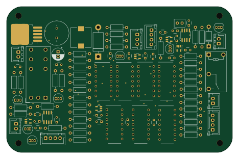
TSAL
116.9 × 75.6 mm99 parts2LNo license0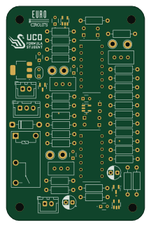
Brake System Plausibility Device
52.3 × 80.9 mm65 parts2LNo license0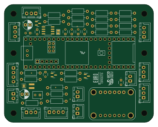 NXP
NXPBreakout
81.4 × 64.3 mm52 parts2LNo license0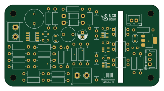
Voltage Measurement KR
81.2 × 42.7 mm52 parts2LNo license0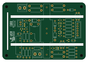
Precharge Board
88.7 × 61 mm51 parts2LNo license0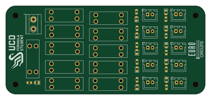
PDU KR
104.2 × 45.9 mm44 parts2LNo license0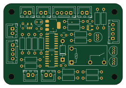
Charger Shutdown KR
65.1 × 44.3 mm41 parts2LNo license0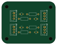
APPS final
48.9 × 38.5 mm12 parts2LNo license0