
Rm electrical chassis

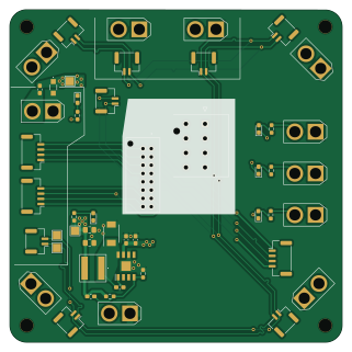
About the Rm electrical chassis PCB
Rm electrical chassis is an open source PCB design by ut-ras, published on GitHub. It is a 4-layer board measuring 80 × 80.1 mm, with 47 components from 36 distinct parts.
Other key parts include the RT6285GSP. By type, the board carries 24 connectors, 7 diodes, 7 resistors, 6 capacitors, 1 IC and 1 fuse.
From the project
This project contains the chassis board, which routes power and CAN to the wheels from the PMM and the Dev Board, respectively. Also, a buck converter that drives the 19V power needed for the CV board. This is sent up the slip ring.
Main components on the Rm electrical chassis
Rm electrical chassis bill of materials (BOM)
47 components, 36 distinct parts — part numbers from the project's BOM.
| Qty | Part | Footprint | Refs |
|---|---|---|---|
| 1 | RT6285GSP | SOIC127P600X175-9N | IC2 |
| 1 | JST 2-pin FR_JST | JST_GH_BM02B-GHS-TBT_1x02-1MP_P1.25mm_Vertical | J1 |
| 1 | JST 2-pin BR_JST | JST_GH_BM02B-GHS-TBT_1x02-1MP_P1.25mm_Vertical | J2 |
| 1 | JST 2-pin FL_JST | JST_GH_BM02B-GHS-TBT_1x02-1MP_P1.25mm_Vertical | J3 |
| 1 | JST 2-pin BL_JST | JST_GH_BM02B-GHS-TBT_1x02-1MP_P1.25mm_Vertical | J4 |
| 1 | XT30 FR_XT30 | AMASS_XT30U-F_1x02_P5.0mm_Vertical | J5 |
| 1 | XT30 BR_XT30 | AMASS_XT30U-F_1x02_P5.0mm_Vertical | J6 |
| 1 | XT30 FL_XT30 | AMASS_XT30U-F_1x02_P5.0mm_Vertical | J7 |
| 1 | XT30 BL_XT30 | AMASS_XT30U-F_1x02_P5.0mm_Vertical | J8 |
| 1 | JST 2-pin IN_JST | JST_GH_BM02B-GHS-TBT_1x02-1MP_P1.25mm_Vertical | J9 |
| 1 | XT30 IN_XT30 | AMASS_XT30U-F_1x02_P5.0mm_Vertical | J10 |
| 3 | JST 4-pin Conn_01x04 | JST_GH_BM04B-GHS-TBT_1x04-1MP_P1.25mm_Vertical | J11, J23, J25 |
| 2 | XT30 SUPCAP_XT30 | AMASS_XT30U-F_1x02_P5.0mm_Vertical | J12, J29 |
| 1 | JST 2-pin GIM1_JST | JST_GH_BM02B-GHS-TBT_1x02-1MP_P1.25mm_Vertical | J13 |
| 1 | JST 2-pin GIM2_JST | JST_GH_BM02B-GHS-TBT_1x02-1MP_P1.25mm_Vertical | J14 |
| 1 | XT30 GIM1_XT30 | AMASS_XT30U-F_1x02_P5.0mm_Vertical | J15 |
| 1 | XT30 GIM2_XT30 | AMASS_XT30U-F_1x02_P5.0mm_Vertical | J16 |
| 1 | 501645-1620 | 5016451620 | J17 |
| 1 | XT30 SHOO_XT30 | AMASS_XT30U-F_1x02_P5.0mm_Vertical | J19 |
| 1 | XT30 GIM_XT30 | AMASS_XT30U-F_1x02_P5.0mm_Vertical | J20 |
Show 16 more
| Qty | Part | Footprint | Refs |
|---|---|---|---|
| 1 | JST 2-pin CAN2_IN | JST_GH_BM02B-GHS-TBT_1x02-1MP_P1.25mm_Vertical | J27 |
| 1 | 172298-1108 Conn_01x08 | 172298-YY08 | J31 |
| 1 | ERB-RE2R50V 2.5A | Fuse_0603_1608Metric_Pad1.05x0.95mm_HandSolder | F1 |
| 1 | 150060BS75000 | LED_0603_1608Metric_Pad1.05x0.95mm_HandSolder | D1 |
| 1 | 150060RS75000 | LED_0603_1608Metric_Pad1.05x0.95mm_HandSolder | D2 |
| 1 | SR54F-AU_R2_000A1 | SODFL5336X110N | D4 |
| 3 | 150060YS75000 | LED_0603_1608Metric_Pad1.05x0.95mm_HandSolder | D7, D9, D11 |
| 1 | PTVS26VS1UR-QX | PTVS26VS1URQX | D10 |
| 1 | MPL-AL6060-100 10µH | MPLAL6060100 | L1 |
| 1 | C0603C103J5RACAUTO 0.01u | C_0603_1608Metric_Pad1.08x0.95mm_HandSolder | C1 |
| 1 | CC0603FRNPO0BN820 82pF | C_0603_1608Metric_Pad1.08x0.95mm_HandSolder | C3 |
| 2 | CL21A226MAYNNNE 22µF | C_0805_2012Metric_Pad1.18x1.45mm_HandSolder | C5, C6 |
| 2 | C1608X5R1E475K080AC 4.7µF | C_0603_1608Metric_Pad1.08x0.95mm_HandSolder | C7, C8 |
| 5 | RT0603DRD071KL 1kΩ | R_0603_1608Metric_Pad0.98x0.95mm_HandSolder | R1, R2, R8, R10, R12 |
| 1 | RT0603DRE07100KL 100kΩ | R_0603_1608Metric_Pad0.98x0.95mm_HandSolder | R3 |
| 1 | RT0603DRE076K8L 6.8kΩ | R_0603_1608Metric_Pad0.98x0.95mm_HandSolder | R4 |
Rm electrical chassis design files
The KiCad project lives in the ut-ras/rm_electrical-chassis repository on GitHub; these links point at the commit this page was built from.
- LayoutChassis.kicad_pcb
- SchematicChassis.kicad_sch
- BOMbom/chassis_bom.csv
Rm electrical chassis: common questions
How big is the Rm electrical chassis PCB?
The Rm electrical chassis measures 80 × 80.1 mm, has 4 copper layers and is 1.6 mm thick.
How many components are on the Rm electrical chassis?
47 components, from 36 distinct parts, with part numbers taken from the project's own BOM. The full bill of materials is listed on this page.
Where can I download the Rm electrical chassis design files?
From the ut-ras/rm_electrical-chassis repository on GitHub, which has the KiCad layout, the schematic and the BOM; the links under Design files point to each one.
Can I use the Rm electrical chassis design in my own project?
The repository has no license, so all rights stay with ut-ras. Use it as a reference, and ask the author before reusing the design.