
LoRa-GPS-Tracker

About the LoRa-GPS-Tracker PCB
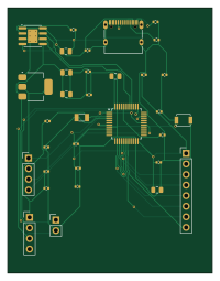
LoRa-GPS-Tracker is an open source STM32 PCB design by Abhi90808, published on GitHub. It is a 2-layer board measuring 49.2 × 63.6 mm, with 33 components from 16 distinct parts.
Its main chip is the STM32L051C8T6, from the STM32 family. Other key parts include the TP4056 and AMS1117-3.3. By type, the board carries 18 capacitors, 5 connectors, 5 resistors, 3 ICs, 1 crystal and 1 switch.
It belongs with the rf & radio, iot & wireless and power & battery designs in this gallery.
From the project
Custom PCB GPS tracker using LoRa wireless communication for long-range asset tracking with low power consumption.
A custom PCB GPS tracker using LoRa wireless communication for long-range, low-power asset tracking. Designed in KiCad 8, combining a GPS module and LoRa transceiver for remote location reporting.
The GPS module sends NMEA sentences via UART to the MCU. The MCU parses the latitude/longitude and transmits it as a LoRa packet. A receiver node (another LoRa module or a LoRaWAN gateway) picks up the packet and logs or displays the location.
Main components on the LoRa-GPS-Tracker
LoRa-GPS-Tracker bill of materials (BOM)
33 components, 16 distinct parts.
| Qty | Part | Footprint | Refs |
|---|---|---|---|
| 1 | TP4056 | SOIC-8-1EP_3.9x4.9mm_P1.27mm_EP2.41x3.3mm_ThermalVias | U1 |
| 1 | AMS1117-3.3 | SOT-223-3_TabPin2 | U2 |
| 1 | STM32L051C8T6 | LQFP-48_7x7mm_P0.5mm | U3 |
| 1 | 32.768kHz | Crystal_SMD_3215-2Pin_3.2x1.5mm | Y1 |
| 1 | USB_C | USB_C_Receptacle_XKB_U262-16XN-4BVC11 | J1 |
| 1 | BATTERY | PinHeader_1x02_P2.54mm_Vertical | J2 |
| 1 | NEO6M_GPS | PinHeader_1x04_P2.54mm_Vertical | J3 |
| 1 | SX1276_LORA | PinHeader_1x08_P2.54mm_Vertical | J4 |
| 1 | SWD_DEBUG | PinHeader_1x04_P2.54mm_Vertical | J5 |
| 1 | RESET | SW_SPST_B3U-1000P | SW1 |
| 5 | 10uf | C_0805_2012Metric | C1, C3, C5, C7, C11 |
| 8 | 100nf | C_0402_1005Metric | C2, C4, C6, C8, C9, C10, C12, C15 |
| 5 | 12pf | C_0402_1005Metric | C13, C14, C16, C17, C18 |
| 2 | 5.1k | R_0402_1005Metric | R1, R2 |
| 1 | 1.2k | R_0402_1005Metric | R3 |
| 2 | 10k | R_0402_1005Metric | R4, R5 |
LoRa-GPS-Tracker design files
The KiCad project lives in the Abhi90808/LoRa-GPS-Tracker repository on GitHub; these links point at the commit this page was built from.
- Layoutlora_gps_tracker.kicad_pcb
- Schematiclora_gps_tracker.kicad_sch
LoRa-GPS-Tracker: common questions
What microcontroller does the LoRa-GPS-Tracker use?
The LoRa-GPS-Tracker is built around the STM32L051C8T6, from the STM32 family.
How big is the LoRa-GPS-Tracker PCB?
The LoRa-GPS-Tracker measures 49.2 × 63.6 mm, has 2 copper layers and is 1.6 mm thick.
How many components are on the LoRa-GPS-Tracker?
33 components, from 16 distinct parts. The full bill of materials is listed on this page.
Where can I download the LoRa-GPS-Tracker design files?
From the Abhi90808/LoRa-GPS-Tracker repository on GitHub, which has the KiCad layout and the schematic; the links under Design files point to each one.
Can I use the LoRa-GPS-Tracker design in my own project?
The repository has no license, so all rights stay with Abhi90808. Use it as a reference, and ask the author before reusing the design.
Can I test firmware for the LoRa-GPS-Tracker without the hardware?
Yes. HardLabs builds a simulation of the board from its netlist and BOM, so you can run and debug STM32 firmware against it before you order a PCB.
Similar boards
 STM32
STM32LumenPnP Motherboard
opulo-inc
149 × 95 mm296 parts4LCC-BY-SA-4.03.7k STM32
STM32AxxSolder
AxxAxx
39 × 82.5 mm122 parts2LGPL-3.01.7k STM32
STM32AIOC
skuep
21 × 31.5 mm47 parts2LMIT1.4k STM32
STM32Ferris
pierrechevalier83
208.8 × 86.8 mm102 parts2LSHL-2.11.3k STM32
STM32176 pin board
rusefi
61.8 × 73.2 mm76 parts2LGPL-3.01.2k STM32
STM32Brain board STM32F407
61.8 × 73.2 mm69 parts2LGPL-3.01.2k