
Alternator 555 timer

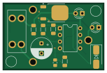
About the Alternator 555 timer PCB
Alternator 555 timer is an open source PCB design by alexanderenrique, published on GitHub. It is a 2-layer board measuring 38.1 × 25.4 mm, with 18 components from 16 distinct parts.
Other key parts include the TLC555CP. By type, the board carries 4 diodes, 4 capacitors, 4 resistors, 3 connectors, 1 IC and 1 transistor.
From the project
CMOS 555 monostable delay circuit for alternator field excitation
A small analog delay board for classic cars with upgraded alternators. A CMOS 555 monostable holds the alternator field (I wire) off for ~10 seconds after key-on so V-belts can spin up before the load hits — no MCU, no firmware.
Project page: denton.works/projects/alternator-555-timer
- KiCad schematic and PCB (555Idelay.kicad) - BOM.csv — bill of materials - 555v1.zip` — zipped gerbers and drill files for your PCB manufacturer
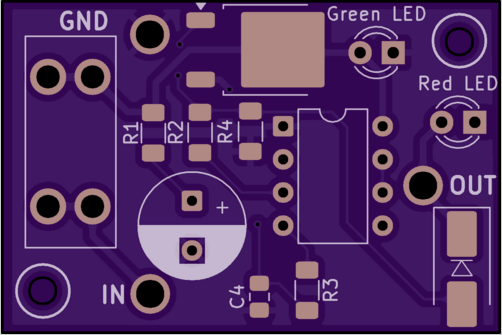
Main components on the Alternator 555 timer
Alternator 555 timer bill of materials (BOM)
18 components, 16 distinct parts — part numbers from the project's BOM.
| Qty | Part | Footprint | Refs |
|---|---|---|---|
| 1 | TLC555CP NE555P | DIP-8_W7.62mm | U1 |
| 1 | FQD11P06TM | TO-252-2 | Q1 |
| 1 | I_In | PinHeader_1x01_P1.00mm_Vertical | J1 |
| 1 | I_out | 12_AWG_TH_Alex | J2 |
| 1 | GND_Conn | 12_AWG_TH_Alex | J3 |
| 1 | Fuse_Small | Fuseholder_Blade_Mini_Keystone_3568 | F1 |
| 1 | SZ1SMB15AT3G TVS | D_SMB_Handsoldering | D1 |
| 1 | SZ1SMB15AT3G BZV55B15 | D_SMB_Handsoldering | D2 |
| 1 | Green LED | LED_D3.0mm_Clear | D3 |
| 1 | Red LED | LED_D3.0mm_Clear | D4 |
| 3 | 0.1UF 0.1uF | C_0805_2012Metric_Pad1.18x1.45mm_HandSolder | C1, C3, C4 |
| 1 | 47UF 47uF | CP_Radial_D8.0mm_P3.80mm | C2 |
| 1 | 220K 220k | R_1206_3216Metric_Pad1.30x1.75mm_HandSolder | R1 |
| 1 | 100 | R_1206_3216Metric_Pad1.30x1.75mm_HandSolder | R2 |
| 1 | 10K 10k | R_1206_3216Metric_Pad1.30x1.75mm_HandSolder | R3 |
| 1 | 100K 100k (pulldown) | R_1206_3216Metric_Pad1.30x1.75mm_HandSolder | R4 |
Alternator 555 timer design files
The KiCad project lives in the alexanderenrique/alternator_555_timer repository on GitHub; these links point at the commit this page was built from.
- Layout555_I_delay.kicad_pcb
- Schematic555_I_delay.kicad_sch
- BOMBOM.csv
Alternator 555 timer: common questions
How big is the Alternator 555 timer PCB?
The Alternator 555 timer measures 38.1 × 25.4 mm, has 2 copper layers and is 1.6 mm thick.
How many components are on the Alternator 555 timer?
18 components, from 16 distinct parts, with part numbers taken from the project's own BOM. The full bill of materials is listed on this page.
Where can I download the Alternator 555 timer design files?
From the alexanderenrique/alternator_555_timer repository on GitHub, which has the KiCad layout, the schematic and the BOM; the links under Design files point to each one.
Can I use the Alternator 555 timer design in my own project?
The repository has no license, so all rights stay with alexanderenrique. Use it as a reference, and ask the author before reusing the design.