
PhaseLatchMini

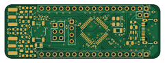
About the PhaseLatchMini PCB
PhaseLatchMini is an open source STM32 PCB design by AndersBNielsen, published on GitHub. It is a 4-layer board measuring 60.2 × 20.8 mm, with 63 components from 28 distinct parts.
Its main chip is the STM32F103C8TX, from the STM32 family. Other key parts include the MIC5504-3.3YM5. By type, the board carries 23 capacitors, 19 resistors, 8 connectors, 7 inductors, 2 ICs and 2 crystals.
It belongs with the rf & radio designs in this gallery.
From the project
High-rate continuous streaming of interleaved dual ADC (I/Q) samples over USB Full‑Speed (FS) using only the built‑in CDC class on an STM32F103C8 ("Blue Pill" style) board. Companion Python host tools provide live visualization, FIFO bridging, raw capture, diagnostics, and throughput benchmarking.
High-rate continuous streaming of interleaved dual ADC (I/Q) samples over USB Full‑Speed (FS) using only the built‑in CDC class on an STM32F103C8 ("Blue Pill" style) board. Companion Python host tools provide live visualization, FIFO bridging, raw capture, diagnostics, and throughput benchmarking.
https://www.youtube.com/watch?v=UEAtSE1PV44
Direct link (relative): hardware/PhaseLatchMini/production/PhaseLatchMini.zip
Main components on the PhaseLatchMini
PhaseLatchMini bill of materials (BOM)
63 components, 28 distinct parts — part numbers from the project's BOM.
| Qty | Part | Footprint | Refs |
|---|---|---|---|
| 1 | STM32F103C8TX STM32F103C8Tx | LQFP-48_7x7mm_P0.5mm | U1 |
| 1 | MIC5504-3.3YM5 | SOT-23-5 | U5 |
| 1 | 8MHZ 8MHz | Crystal_SMD_3225-4Pin_3.2x2.5mm | Y1 |
| 1 | 32768HZ 32768Hz | Crystal_SMD_3215-2Pin_3.2x1.5mm | Y2 |
| 2 | CONN_01X17_PIN Conn_01x17_Pin | PinHeader_1x17_P2.54mm_Vertical | J1, J3 |
| 1 | NC | PinHeader_1x04_P2.54mm_Vertical | J2 |
| 1 | USB2.0_16P | USB_C_Receptacle_HCTL_HC-TYPE-C-16P-01A | J4 |
| 1 | Boot | PinHeader_2x03_P2.54mm_Vertical | J5 |
| 1 | NC | PinHeader_1x02_P2.54mm_Vertical | J6 |
| 1 | C5301850 I_IN | SMA_Samtec_SMA-J-P-H-ST-EM1_EdgeMount | J20 |
| 1 | C5301850 Q_IN | SMA_Samtec_SMA-J-P-H-ST-EM1_EdgeMount | J21 |
| 1 | C318884 BTN | SW_SPST_TL3342 | SW3 |
| 1 | C2297 GREEN | LED_0805_2012Metric | D1 |
| 1 | C14709 FerriteBead_Small | L_0603_1608Metric | FB1 |
| 6 | 10UH 10uH | L_0805_2012Metric | L1, L2, L3, L4, L5, L6 |
| 7 | 100NF 100nF | C_0402_1005Metric | C1, C8, C9, C10, C11, C16, C23 |
| 2 | 15PF 15pF | C_0402_1005Metric | C2, C3 |
| 2 | 18PF 18pF | C_0402_1005Metric | C4, C7 |
| 4 | 1UF 1uF | C_0805_2012Metric | C5, C6, C12, C13 |
| 4 | 22NF 22nF | C_0402_1005Metric | C14, C15, C20, C22 |
Show 8 more
| Qty | Part | Footprint | Refs |
|---|---|---|---|
| 2 | 470NF 470nF | C_0603_1608Metric | C17, C18 |
| 2 | 220NF 220nF | C_0402_1005Metric | C19, C21 |
| 4 | 10K 10k | R_0402_1005Metric | R1, R2, R4, R7 |
| 1 | 1K5 1k5 | R_0402_1005Metric | R3 |
| 6 | 4.7 | R_0603_1608Metric | R5, R6, R8, R10, R11, R12 |
| 2 | 10 | R_0603_1608Metric | R9, R15 |
| 2 | 5K1 5k1 | R_0402_1005Metric | R13, R14 |
| 4 | C25867 NC | R_0402_1005Metric | R17, R18, R19, R20 |
PhaseLatchMini design files
The KiCad project lives in the AndersBNielsen/PhaseLatchMini repository on GitHub; these links point at the commit this page was built from.
PhaseLatchMini: common questions
What microcontroller does the PhaseLatchMini use?
The PhaseLatchMini is built around the STM32F103C8TX, from the STM32 family.
How big is the PhaseLatchMini PCB?
The PhaseLatchMini measures 60.2 × 20.8 mm, has 4 copper layers and is 1.6 mm thick.
How many components are on the PhaseLatchMini?
63 components, from 28 distinct parts, with part numbers taken from the project's own BOM. The full bill of materials is listed on this page.
Where can I download the PhaseLatchMini design files?
From the AndersBNielsen/PhaseLatchMini repository on GitHub, which has the KiCad layout, the schematic and the BOM; the links under Design files point to each one.
Can I use the PhaseLatchMini design in my own project?
The repository has no license, so all rights stay with AndersBNielsen. Use it as a reference, and ask the author before reusing the design.
Can I test firmware for the PhaseLatchMini without the hardware?
Yes. HardLabs builds a simulation of the board from its netlist and BOM, so you can run and debug STM32 firmware against it before you order a PCB.
Similar boards
 STM32
STM32LumenPnP Motherboard
opulo-inc
149 × 95 mm296 parts4LCC-BY-SA-4.03.7k STM32
STM32AxxSolder
AxxAxx
39 × 82.5 mm122 parts2LGPL-3.01.7k STM32
STM32AIOC
skuep
21 × 31.5 mm47 parts2LMIT1.4k STM32
STM32Ferris
pierrechevalier83
208.8 × 86.8 mm102 parts2LSHL-2.11.3k STM32
STM32Module 16S
stuartpittaway
71.1 × 89.6 mm113 parts4LCC-BY-NC-4.01.1k STM32
STM32Djinn
tzarc
192.3 × 150.5 mm216 parts2LCERN-OHL-S-2.0988