
AT-02-V2

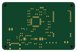
About the AT-02-V2 PCB
AT-02-V2 is an open source STM32 PCB design by ArsenShana, published on GitHub. It is a 4-layer board measuring 68 × 44 mm, with 59 components from 59 distinct parts.
Its main chip is the STM32L072CBT6, from the STM32 family. Other key parts include the u-blox MAX-M10S, EBYTE E32-433T20S, TI BQ24074, TI TPS63031 and ST LIS2DW12. By type, the board carries 21 capacitors, 21 resistors, 8 ICs, 4 connectors, 2 switches and 2 inductors.
It belongs with the rf & radio, power & battery and usb & debug tools designs in this gallery.
From the project
Arduino
Оба проекта — PlatformIO (VS Code → расширение PlatformIO IDE).
В tracker-lab/ добавлены локальный сайт с интерактивной 3D-моделью, симуляция радиообмена, программно разведённая плата-носитель KiCad и корпус STL/STEP. Запуск сайта: cd tracker-lab → npm ci → npm start, затем открыть http://localhost:4173. Инструкция по сборке и прошивке: tracker-lab/README.html.
Main components on the AT-02-V2
AT-02-V2 bill of materials (BOM)
59 components, 59 distinct parts — part numbers from the project's BOM.
| Qty | Part | Footprint | Refs |
|---|---|---|---|
| 1 | STM32L072CBT6 | U1 | U1 |
| 1 | u-blox MAX-M10S | U2 | U2 |
| 1 | EBYTE E32-433T20S | U3 | U3 |
| 1 | TI BQ24074 | U4 | U4 |
| 1 | TI TPS63031 | U5 | U5 |
| 1 | ST LIS2DW12 | U6 | U6 |
| 1 | TI TPS22919 | U7 | U7 |
| 1 | USBLC6-2SC6 / ESD | U8 | U8 |
| 1 | USB-C / USB 2.0 | J1 | J1 |
| 1 | LiPo / NTC · 3 контакта | J2 | J2 |
| 1 | GNSS RF / u.FL | J3 | J3 |
| 1 | SWD / pogo | J4 | J4 |
| 1 | BOOT / DFU | SW1 | SW1 |
| 1 | RESET | SW2 | SW2 |
| 1 | Green LED / status | D1 | D1 |
| 1 | Ferrite / analog supply | FB1 | FB1 |
| 1 | Дроссель 2.2 µH | L1 | L1 |
| 1 | 100nF / VDD1 | C1 | C1 |
| 1 | 100nF / VDD24 | C2 | C2 |
| 1 | 100nF / VDD48 | C3 | C3 |
Show 39 more
| Qty | Part | Footprint | Refs |
|---|---|---|---|
| 1 | 100nF / USB VDD | C4 | C4 |
| 1 | 100nF / VDDA | C5 | C5 |
| 1 | 4.7uF / MCU | C6 | C6 |
| 1 | 100nF / reset | C7 | C7 |
| 1 | 100nF / ADC | C8 | C8 |
| 1 | 1uF / GNSS VIO | C9 | C9 |
| 1 | 10uF / GNSS VCC | C10 | C10 |
| 1 | 1uF / GNSS backup | C11 | C11 |
| 1 | 100nF / motion | C12 | C12 |
| 1 | 10uF / motion | C13 | C13 |
| 1 | 10uF / USB IN | C14 | C14 |
| 1 | 10uF / battery | C15 | C15 |
| 1 | 22uF / VSYS | C16 | C16 |
| 1 | 10uF / buck-boost IN | C17 | C17 |
| 1 | 22uF / buck-boost OUT | C18 | C18 |
| 1 | 22uF / buck-boost OUT | C19 | C19 |
| 1 | 100uF / radio buffer | C20 | C20 |
| 1 | 100nF / radio | C21 | C21 |
| 1 | 5.1k / CC1 | R1 | R1 |
| 1 | 5.1k / CC2 | R2 | R2 |
| 1 | 22R / USB D+ | R3 | R3 |
| 1 | 22R / USB D- | R4 | R4 |
| 1 | 10k / BOOT0 | R5 | R5 |
| 1 | 10k / NRST | R6 | R6 |
| 1 | 1M / battery divider | R7 | R7 |
| 1 | 330k / battery divider | R8 | R8 |
| 1 | 10k / I2C SCL | R9 | R9 |
| 1 | 10k / I2C SDA | R10 | R10 |
| 1 | 330R / LED | R11 | R11 |
| 1 | 100k / EN1 default | R12 | R12 |
| 1 | 2.94k / ISET 300mA target | R13 | R13 |
| 1 | 3.24k / ILIM | R14 | R14 |
| 1 | 46.4k / safety timer | R15 | R15 |
| 1 | 1k / ITERM | R16 | R16 |
| 1 | 10k / CHG pullup | R17 | R17 |
| 1 | 100R / GNSS QOD | R18 | R18 |
| 1 | 10k / radio reset pullup | R19 | R19 |
| 1 | 100k / M0 pulldown | R20 | R20 |
| 1 | 100k / M1 pulldown | R21 | R21 |
AT-02-V2 design files
The KiCad project lives in the ArsenShana/GPS-ES32 repository on GitHub; these links point at the commit this page was built from.
AT-02-V2: common questions
What microcontroller does the AT-02-V2 use?
The AT-02-V2 is built around the STM32L072CBT6, from the STM32 family.
How big is the AT-02-V2 PCB?
The AT-02-V2 measures 68 × 44 mm, has 4 copper layers and is 1.2 mm thick.
How many components are on the AT-02-V2?
59 components, from 59 distinct parts, with part numbers taken from the project's own BOM. The full bill of materials is listed on this page.
Where can I download the AT-02-V2 design files?
From the ArsenShana/GPS-ES32 repository on GitHub, which has the KiCad layout, the schematic and the BOM; the links under Design files point to each one.
Can I use the AT-02-V2 design in my own project?
The repository has no license, so all rights stay with ArsenShana. Use it as a reference, and ask the author before reusing the design.
Can I test firmware for the AT-02-V2 without the hardware?
Yes. HardLabs builds a simulation of the board from its netlist and BOM, so you can run and debug STM32 firmware against it before you order a PCB.
More boards in GPS-ES32
Similar boards
 STM32
STM32LumenPnP Motherboard
opulo-inc
149 × 95 mm296 parts4LCC-BY-SA-4.03.7k STM32
STM32AxxSolder
AxxAxx
39 × 82.5 mm122 parts2LGPL-3.01.7k STM32
STM32LibreVNA
jankae
122 × 98 mm592 parts6LGPL-3.01.6k STM32
STM32AIOC
skuep
21 × 31.5 mm47 parts2LMIT1.4k STM32
STM32Ferris
pierrechevalier83
208.8 × 86.8 mm102 parts2LSHL-2.11.3k STM32
STM32176 pin board
rusefi
61.8 × 73.2 mm76 parts2LGPL-3.01.2k