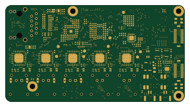
Switch main v5-test rig

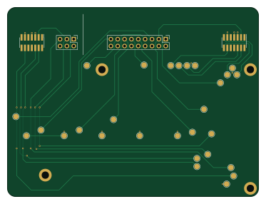
About the Switch main v5-test rig PCB
Switch main v5-test rig is an open source PCB design by ben5049, published on GitHub under the AGPL-3.0 license. It is a 2-layer board measuring 93 × 70 mm, with 4 components from 3 distinct parts.
From the project
KiCad design files for the 5th iteration of my single pair Ethernet (SPE) switch. It is similar to v4 but with more ports and an RJ45 connector so an external media converter isn't needed to connect to regular Ethernet networks.
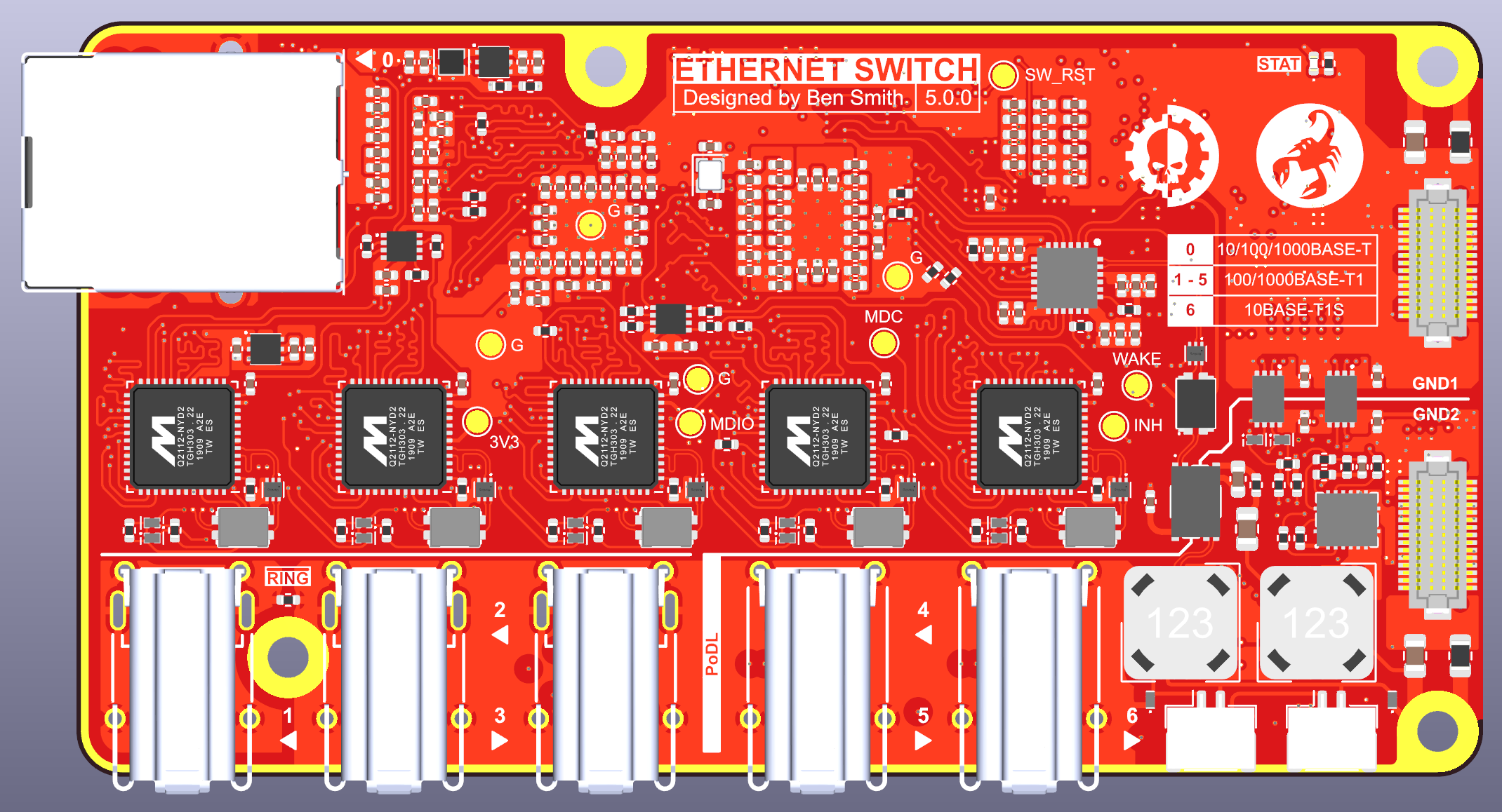
Switch main v5-test rig bill of materials (BOM)
4 components, 3 distinct parts.
| Qty | Part | Footprint | Refs |
|---|---|---|---|
| 2 | Conn_ST_STDC14 | PinHeader_2x07_P1.27mm_Vertical_SMD | J101, J104 |
| 1 | Conn_02x03_Odd_Even | PinHeader_2x03_P2.54mm_Vertical | J103 |
| 1 | Conn_02x09_Odd_Even | PinHeader_2x09_P2.54mm_Vertical | J1001 |
Switch main v5-test rig design files
The KiCad project lives in the ben5049/switch-v5-hardware repository on GitHub; these links point at the commit this page was built from.
Switch main v5-test rig: common questions
How big is the Switch main v5-test rig PCB?
The Switch main v5-test rig measures 93 × 70 mm, has 2 copper layers and is 1.6 mm thick.
How many components are on the Switch main v5-test rig?
4 components, from 3 distinct parts. The full bill of materials is listed on this page.
Where can I download the Switch main v5-test rig design files?
From the ben5049/switch-v5-hardware repository on GitHub, which has the KiCad layout and the schematic; the links under Design files point to each one.
Can I use the Switch main v5-test rig design in my own project?
Yes, under the terms of its AGPL-3.0 license, which ben5049 chose for the repository.