
Inverter ISO Analog

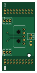
About the Inverter ISO Analog PCB
Inverter ISO Analog is an open source PCB design by columbia-fsae, published on GitHub. It is a 2-layer board measuring 27.8 × 58.4 mm, with 6 components from 6 distinct parts.
Other key parts include the C2000BoosterPack_Shield. By type, the board carries 4 connectors, 1 IC and 1 resistor.
From the project
This repository contains all the PCBs embedded inside the accumulator container of Columbia University's 2021 Formula SAE electric racecar. They were designed in KiCAD by Sabin Zarrandikoetxea and Bert Steyaert.
Main components on the Inverter ISO Analog
Inverter ISO Analog bill of materials (BOM)
6 components, 6 distinct parts.
| Qty | Part | Footprint | Refs |
|---|---|---|---|
| 1 | C2000BoosterPack_Shield | C2000BoosterPack_Shield | U1 |
| 1 | Inverter | Molex_Micro-Fit_3.0_43650-0500_1x05_P3.00mm_Horizontal | J1 |
| 1 | Brake Sensor | Molex_KK-254_AE-6410-03A_1x03_P2.54mm_Vertical | J2 |
| 1 | Motor | Molex_KK-254_AE-6410-02A_1x02_P2.54mm_Vertical | J3 |
| 1 | Accelerator Sensor | Molex_KK-254_AE-6410-03A_1x03_P2.54mm_Vertical | J4 |
| 1 | 330k | R_1206_3216Metric | R1 |
Inverter ISO Analog design files
The KiCad project lives in the columbia-fsae/2021_Accumulator_Electronics repository on GitHub; these links point at the commit this page was built from.
Inverter ISO Analog: common questions
How big is the Inverter ISO Analog PCB?
The Inverter ISO Analog measures 27.8 × 58.4 mm, has 2 copper layers and is 1.6 mm thick.
How many components are on the Inverter ISO Analog?
6 components, from 6 distinct parts. The full bill of materials is listed on this page.
Where can I download the Inverter ISO Analog design files?
From the columbia-fsae/2021_Accumulator_Electronics repository on GitHub, which has the KiCad layout; the links under Design files point to each one.
Can I use the Inverter ISO Analog design in my own project?
The repository has no license, so all rights stay with columbia-fsae. Use it as a reference, and ask the author before reusing the design.
More boards in 2021_Accumulator_Electronics
 AVR/Arduino
Slave Board
412.7 × 77.5 mm148 parts2LNo license1
2021 Accumulator Base
266.4 × 193.2 mm136 parts4LNo license1
AIL TSAL
107.6 × 29.5 mm29 parts2LNo license1
Power Transducer
55.8 × 20.8 mm21 parts2LNo license1
Master slave Connector
143 × 15.5 mm8 parts2LNo license1